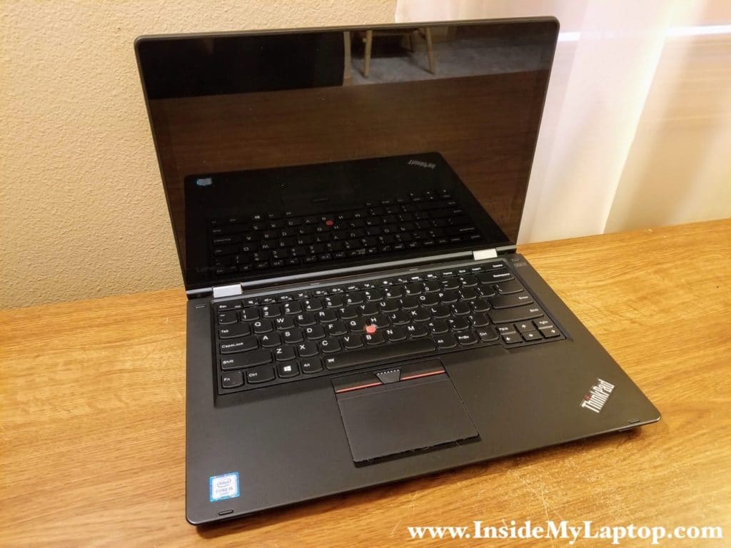
In this guide I’m taking apart a Lenovo ThinkPad Yoga 14 Business Ultrabook (type 20FY).
You can use this guide for taking apart the following models:
– Lenovo ThinkPad Yoga 14.
– Lenovo ThinkPad P40 Yoga.
– Lenovo ThinkPad S3.
– Lenovo ThinkPad Yoga 460.
Removing the keyboard
STEP 1.
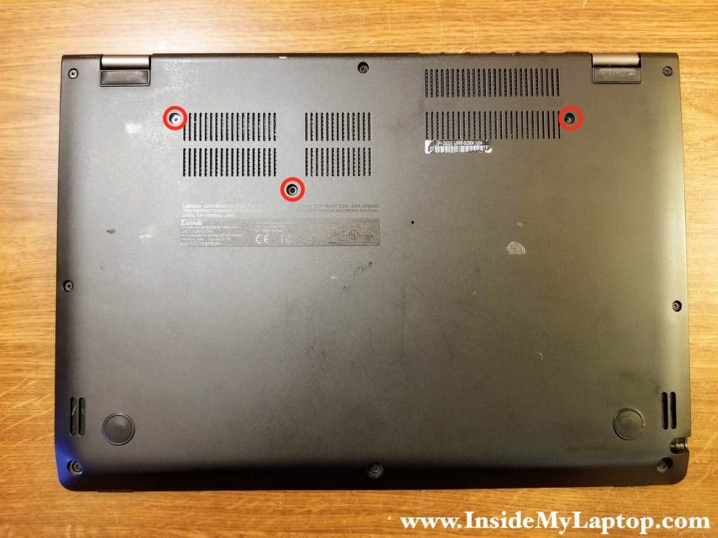
Remove three keyboard screws located on the bottom.
STEP 2.
Slide the keyboard towards the display. The top side of the keyboard will move under the top case bezel. It might be necessary to apply some pressure on the top side of the keyboard to force it under the bezel.
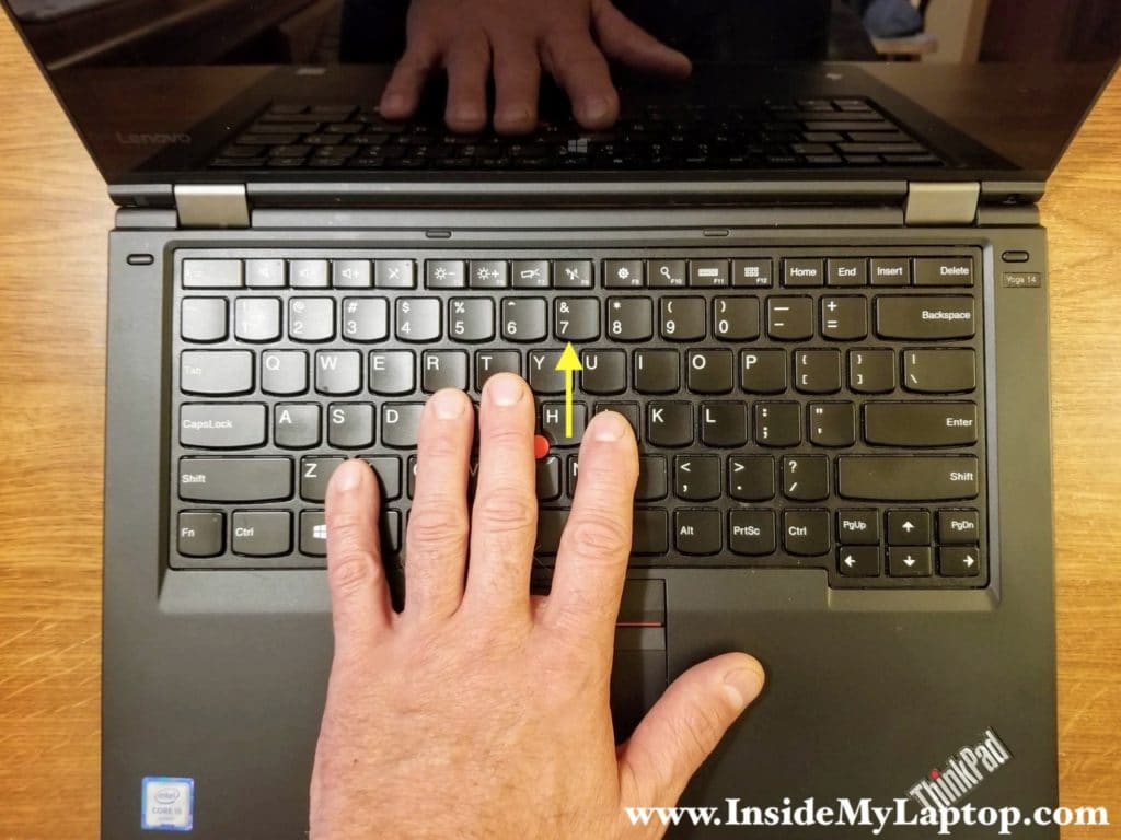
You know you did it properly when you see a gap between the lower side of the keyboard and the palmrest.
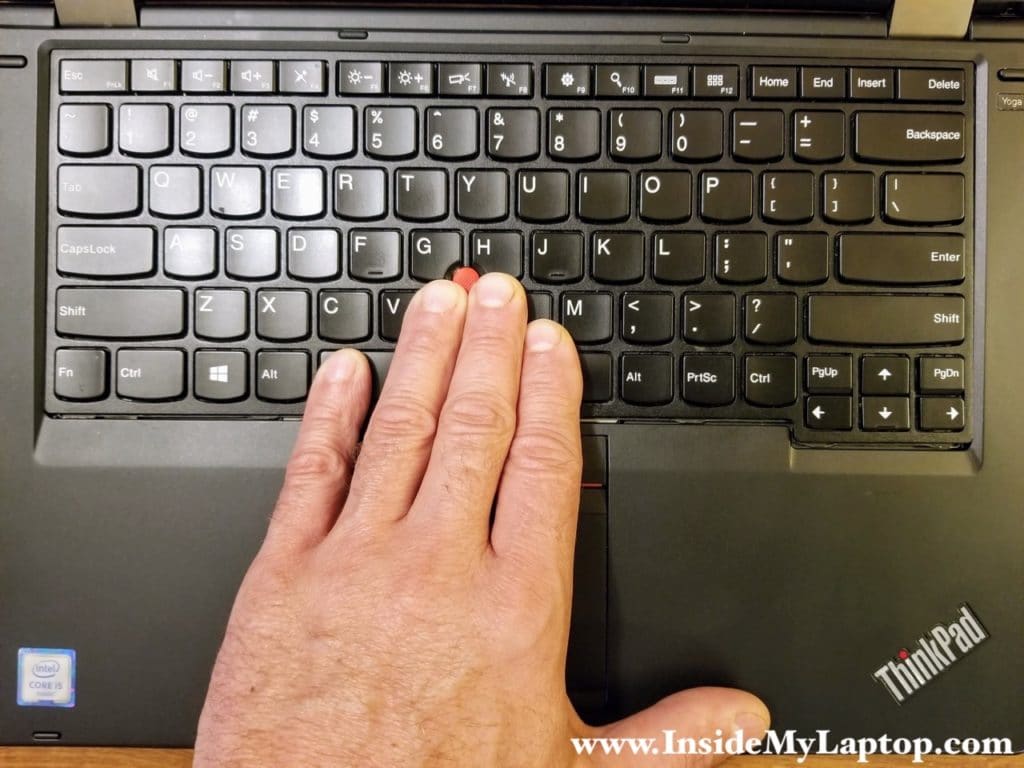
STEP 3.
Lift up the lower side of the keyboard and pull it towards the touchpad. Separate the keyboard from the top case.
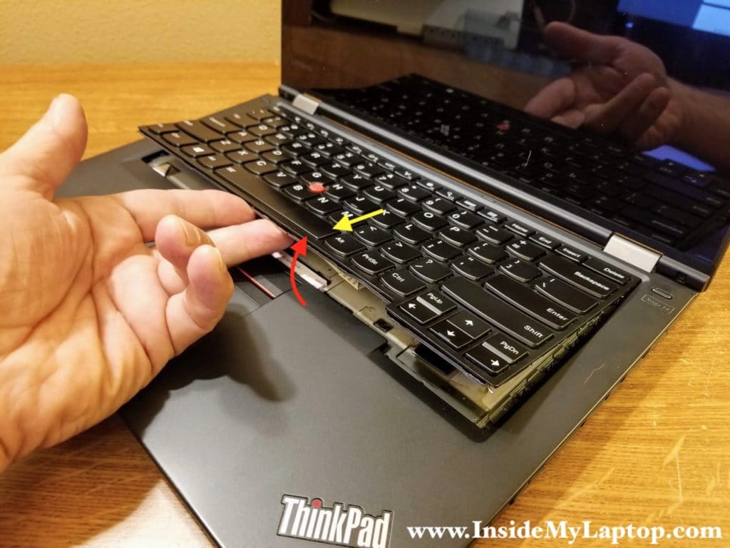
STEP 4.
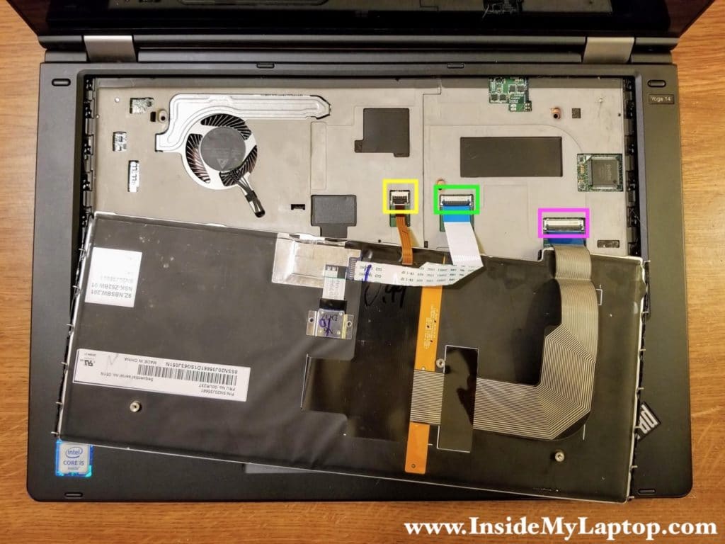
Turn the keyboard upside down and place it on the palmrest. Now you can access and disconnect the following three cables:
– Keyboard backlight cable (yellow).
– Trackpoint cable (green).
– Keyboard cable (pink).
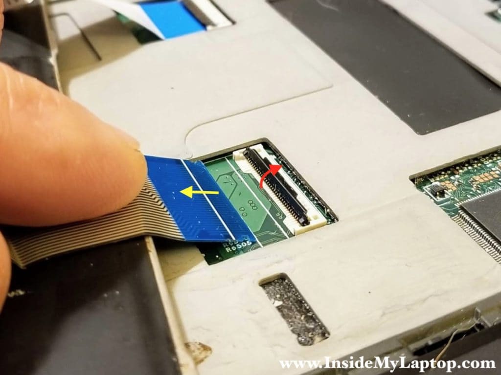
All cable connectors must be unlocked before removing the cables. Lift up the locking tab (red arrow) to unlock the connector. After that lift up the cable and pull it out.
STEP 5.
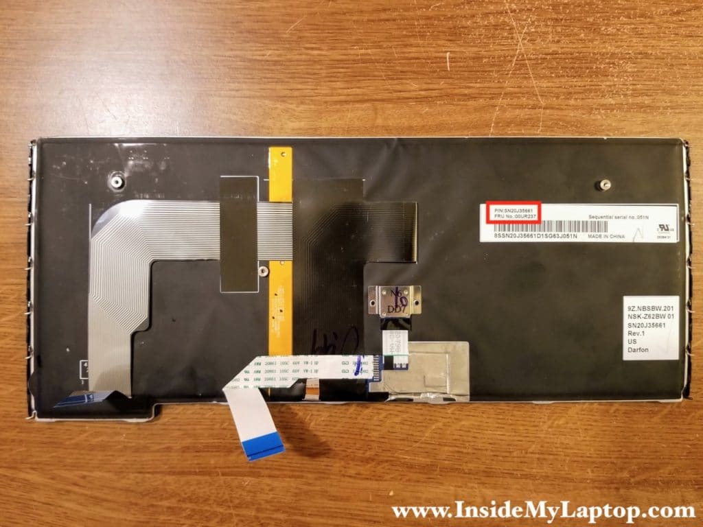
Remove the keyboard. You can find a replacement keyboard by the FRU part number printed on the label. In my case the FRU part number is 00UR237.
STEP 6.
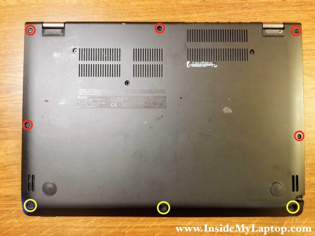
Loosen eight captive screws securing the bottom cover. Three screws on the bottom (yellow) are hidden under the rubber plugs.
STEP 7.
Lift up and remove the bottom cover.
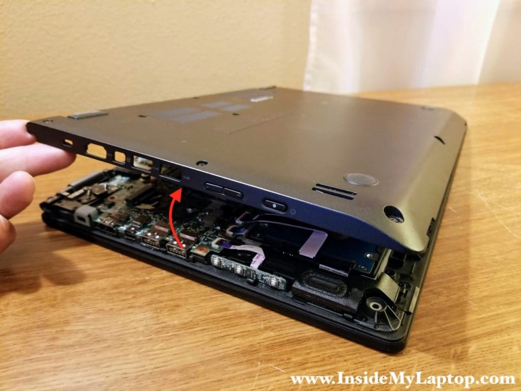
With the bottom cover removed you can access the battery, hard drive, memory slot and other internal components.
Removing the battery
STEP 8.
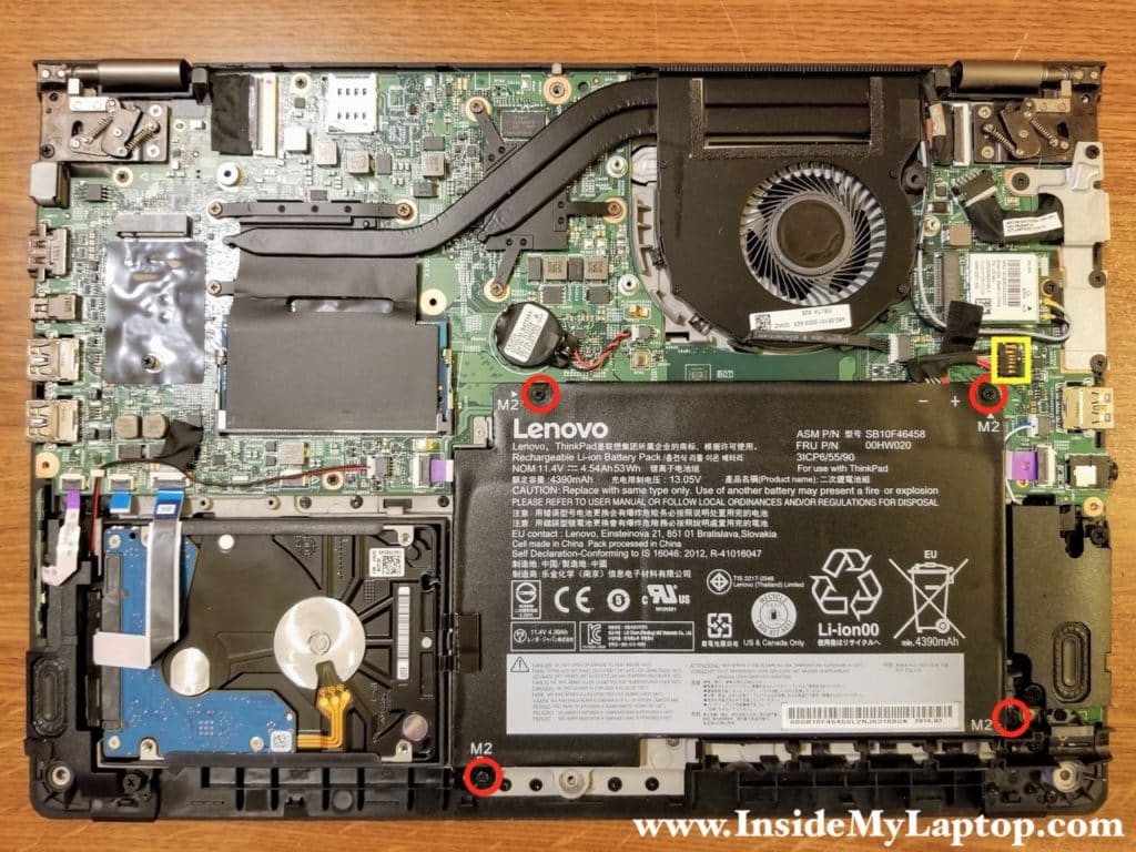
Remove four screws securing the battery and disconnect the battery cable from the motherboard.
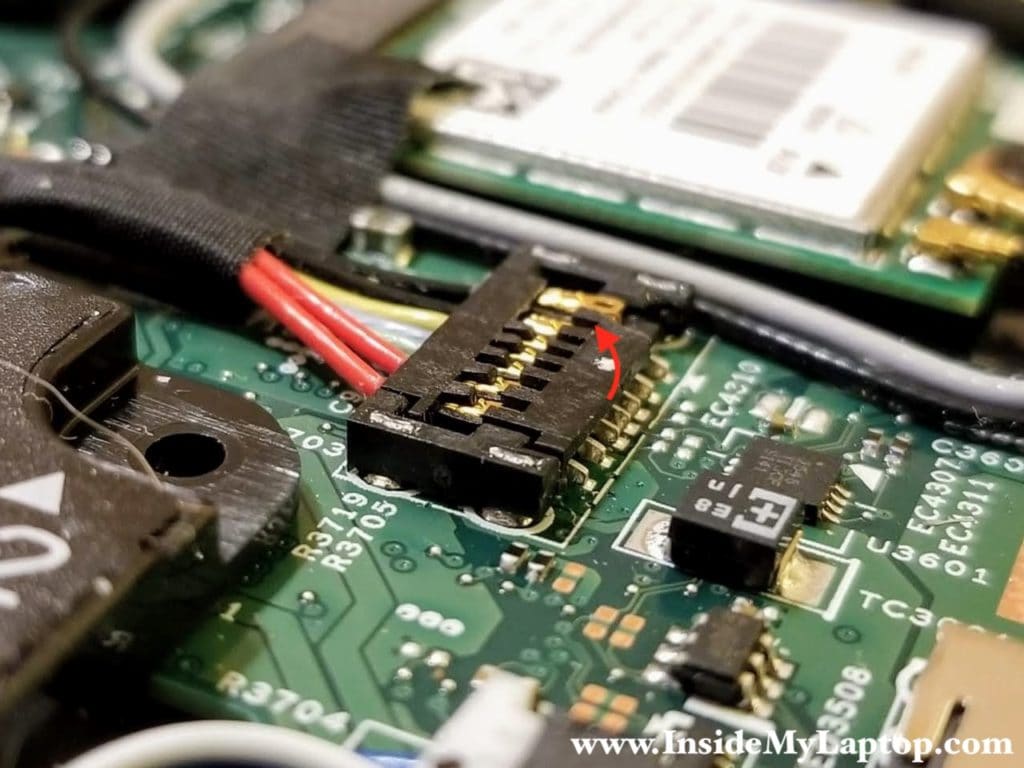
Be careful while disconnecting the battery cable because it has a fragile connector. In my case it was damaged by someone who tried to unlock it incorrectly. In the following steps I’ll show how to properly disconnect the battery.
Carefully lift up the right side of the battery connector (red arrow). I wouldn’t recommend using any metal tools for that. You can accidentally short the pins and damage the battery or the motherboard.
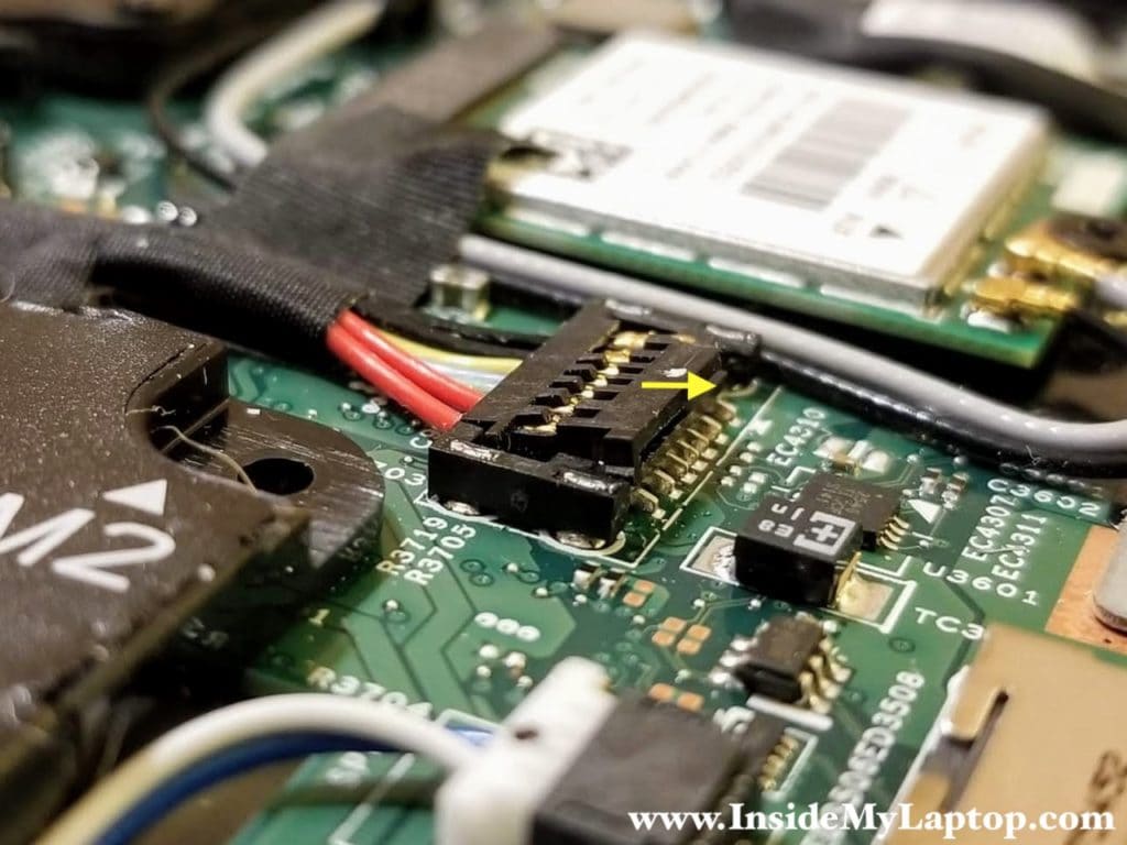
With the right side lifted up, move the cable connector to the right (yellow arrow) to disengage it from the connector on the motherboard.
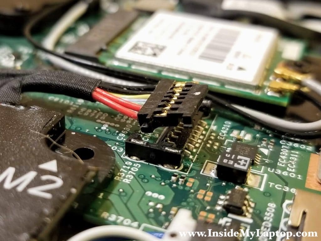
Now the battery cable is disconnected properly.
STEP 9.
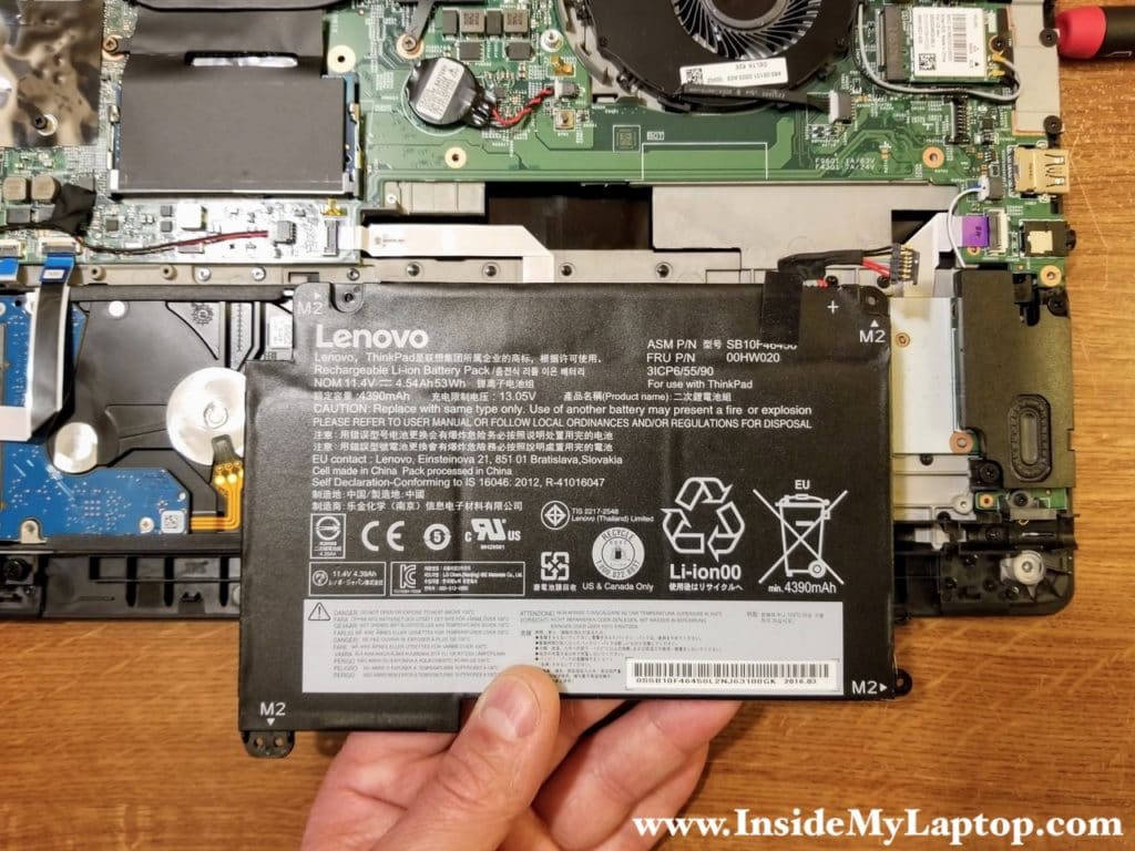
Lift up and remove the battery. Battery FRU number: 00HW020.
Removing internal components
STEP 10.
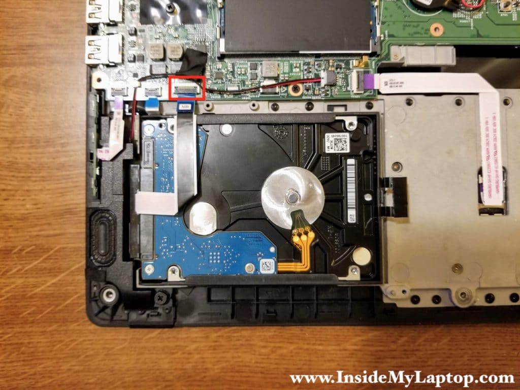
Disconnect the hard drive cable from the motherboard.
STEP 11.
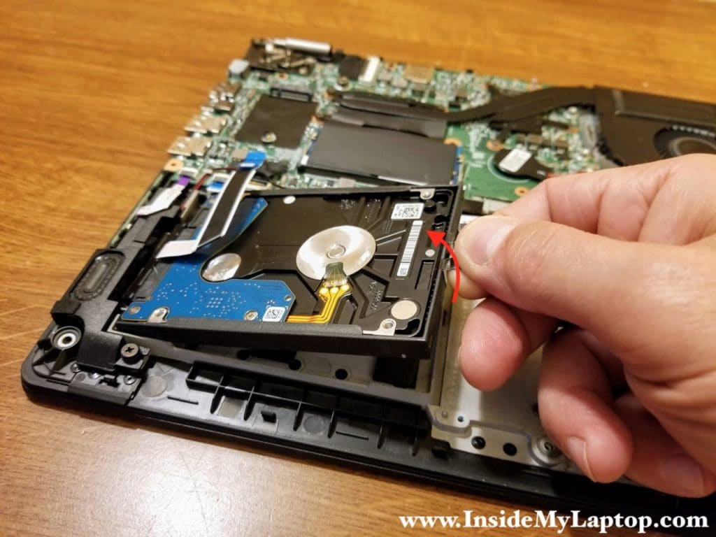
Lift up and remove the hard drive. Upgrading this laptop with a 2.5″ solid state drive will improve the performance significantly.
STEP 12.
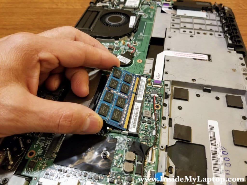
There is only one memory slot. Remove the memory module.
STEP 13.
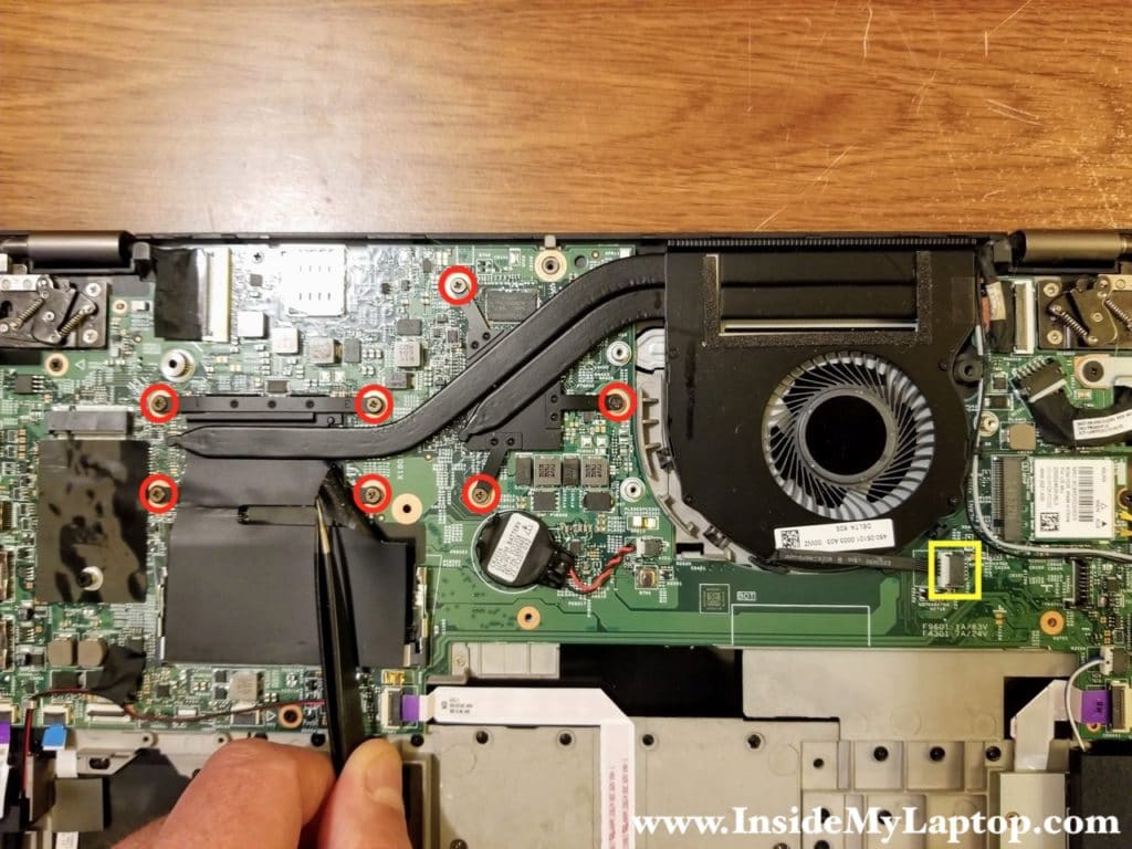
Loosen seven captive screws securing the heatsink/fan assembly. Disconnect the fan cable from the motherboard.
STEP 14.
Lift up and remove the heatsink/fan assembly.
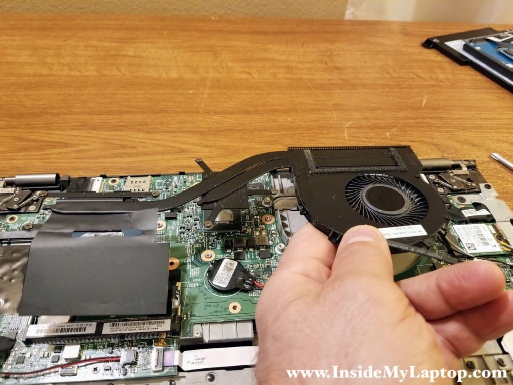
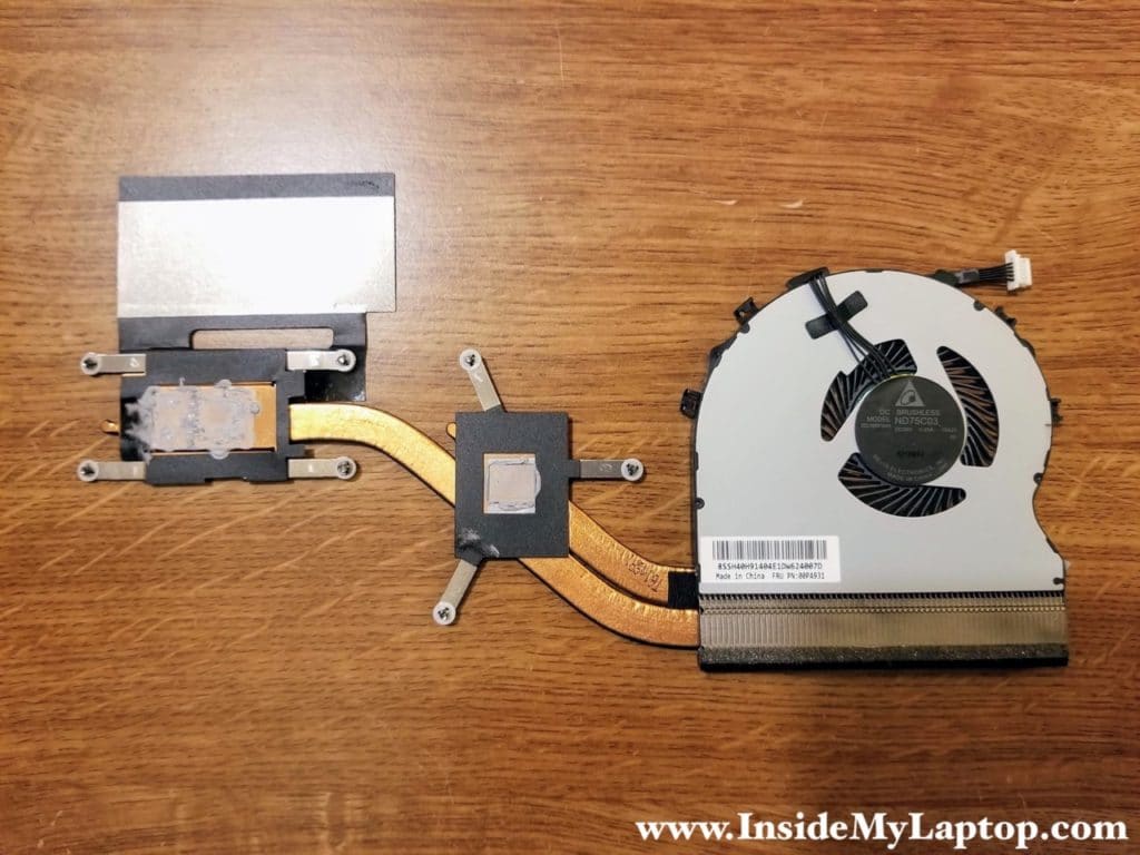
You can find a replacement heatsink/fan assembly if you search by the FRU number printed on the original part. In my case the FRU part number is 00PA931.
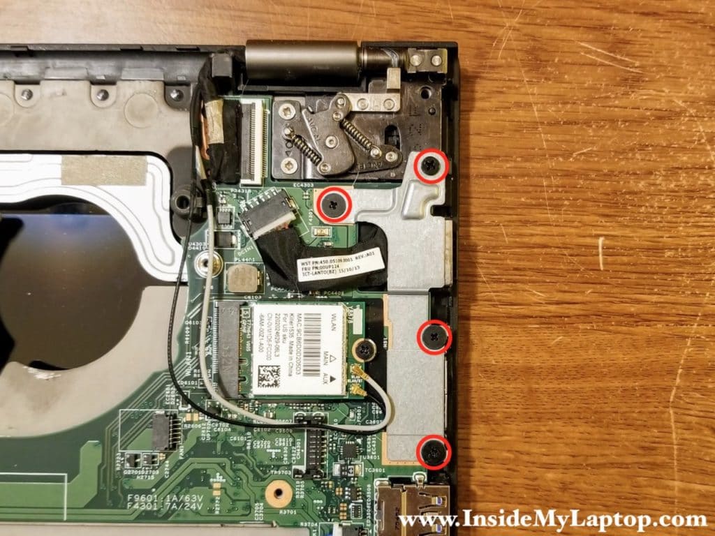
STEP 15.
Remove four screws from the DC jack bracket.
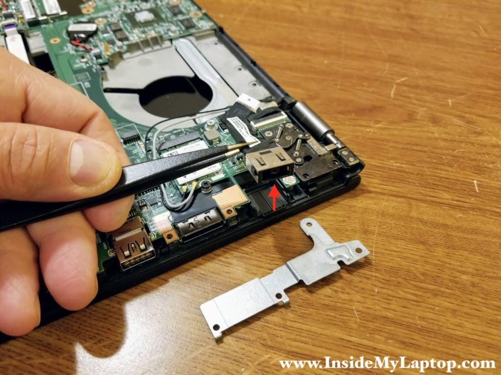
STEP 16.
Remove the metal bracket. Disconnect the DC jack cable from the motherboard and remove it.
STEP 17.
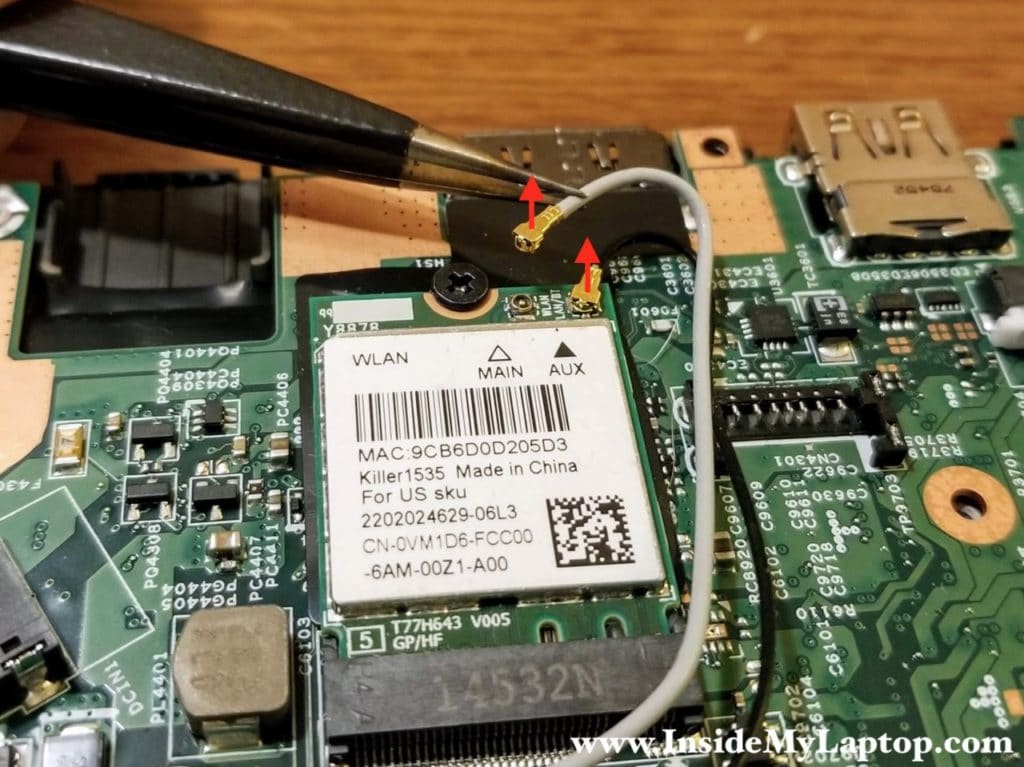
Disconnect two antenna cables from the wireless card. Remove one screw securing the wireless card.
STEP 18.
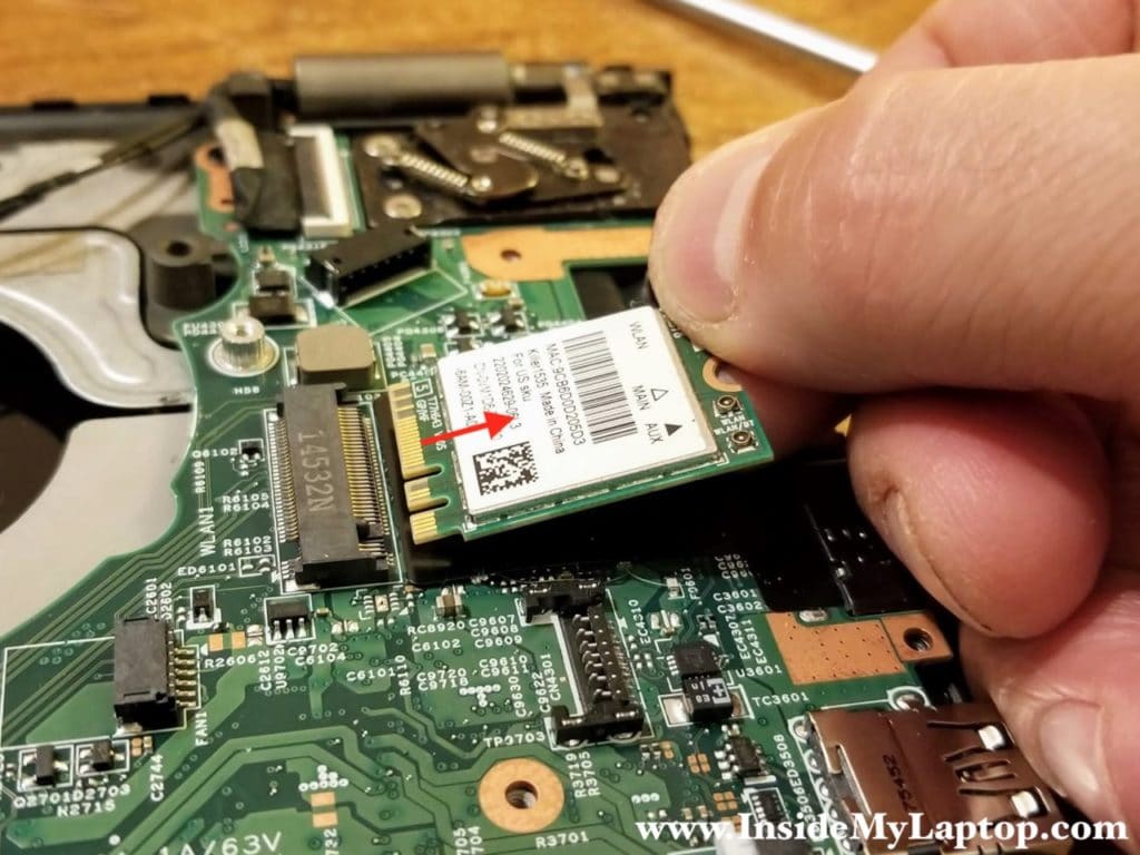
Remove the wireless card.
Removing the display panel
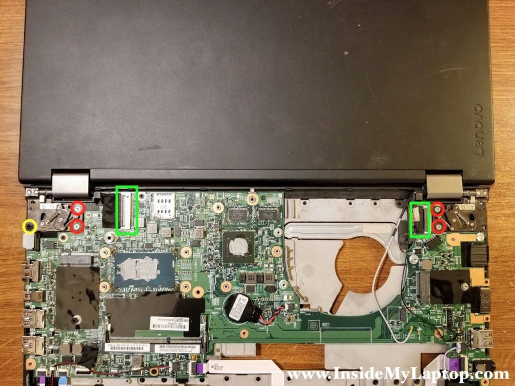
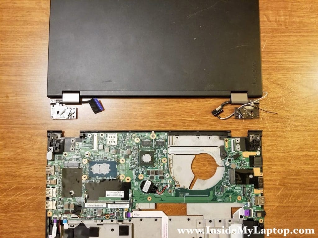
Open the display panel 180 degrees and place the laptop on the desk as it shown on the following picture.
STEP19.
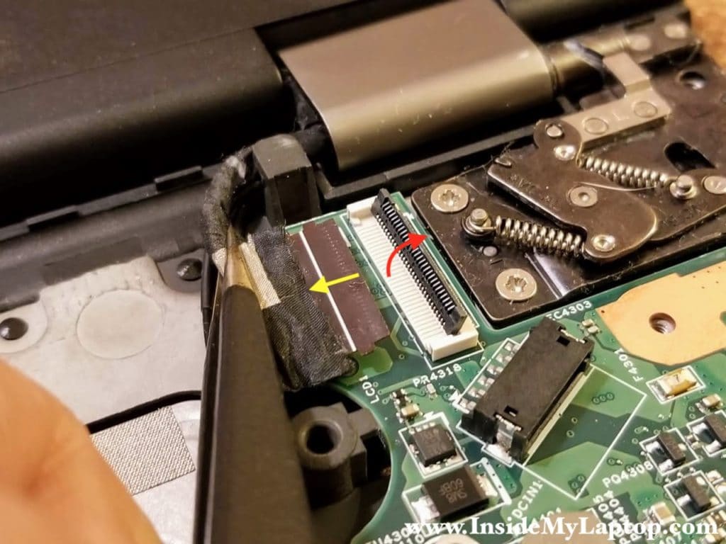
Remove five screws securing the display hinges. Disconnect two display cables from the motherboard.
The display cable connector must be unlocked before removing the cable.
STEP 20.
Separate the display panel from the top case assembly.
In the next guide I will explain how to remove and replace the touchscreen. It is not necessary to remove the display in order to replace the touchscreen.
Removing the motherboard
STEP 21.
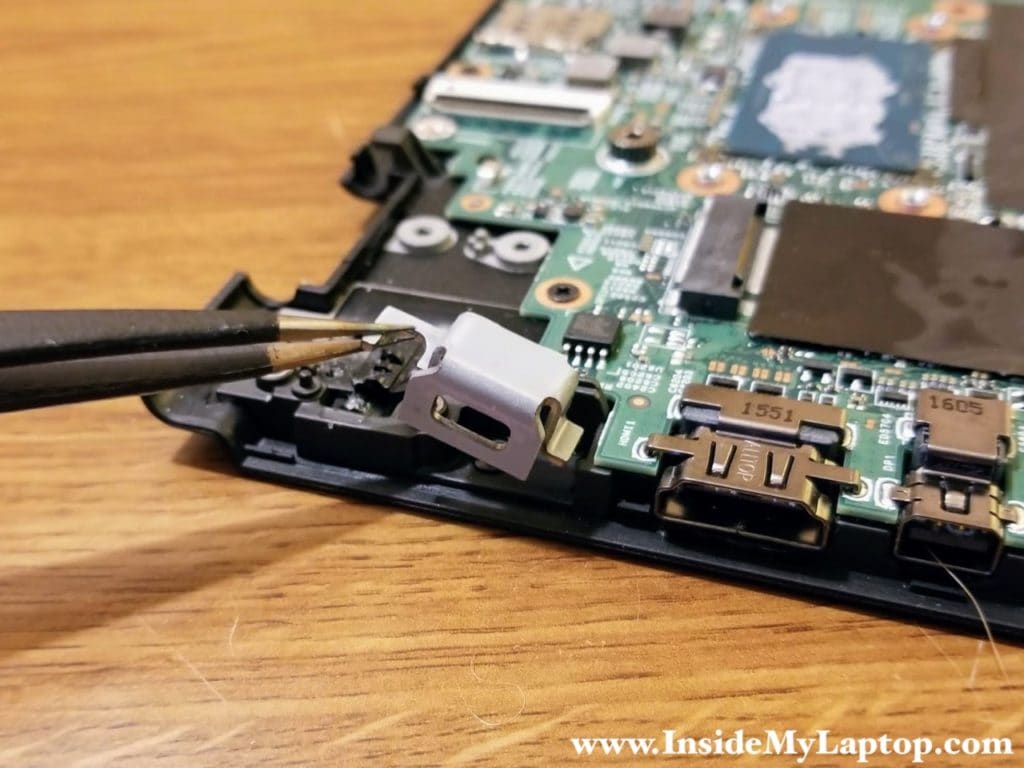
Remove the K-lock bracket.
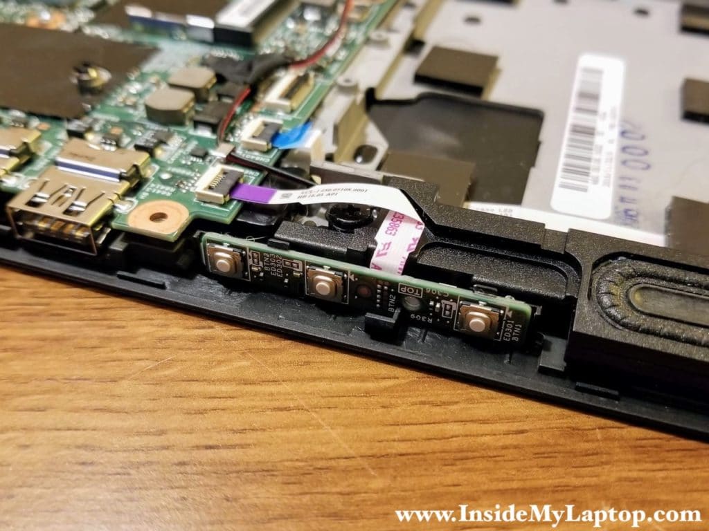
The power button and volume control buttons located on a daughter board. This board can be easily removed and replaced if necessary.
STEP 22.
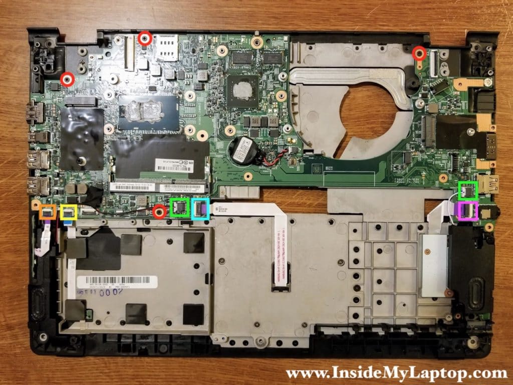
Remove four screws securing the motherboard.
Disconnect the following color-coded cables:
– Power button and volume control board cable (orange).
– ThinkPad logo light cable (yellow).
– Left and right speaker cables (green).
– Touchpad cable (blue).
– Media card reader cable (pink).
I will leave the CMOS battery connected to preserve the BIOS settings.
STEP 23.
Lift up the motherboard and remove it from the top case.
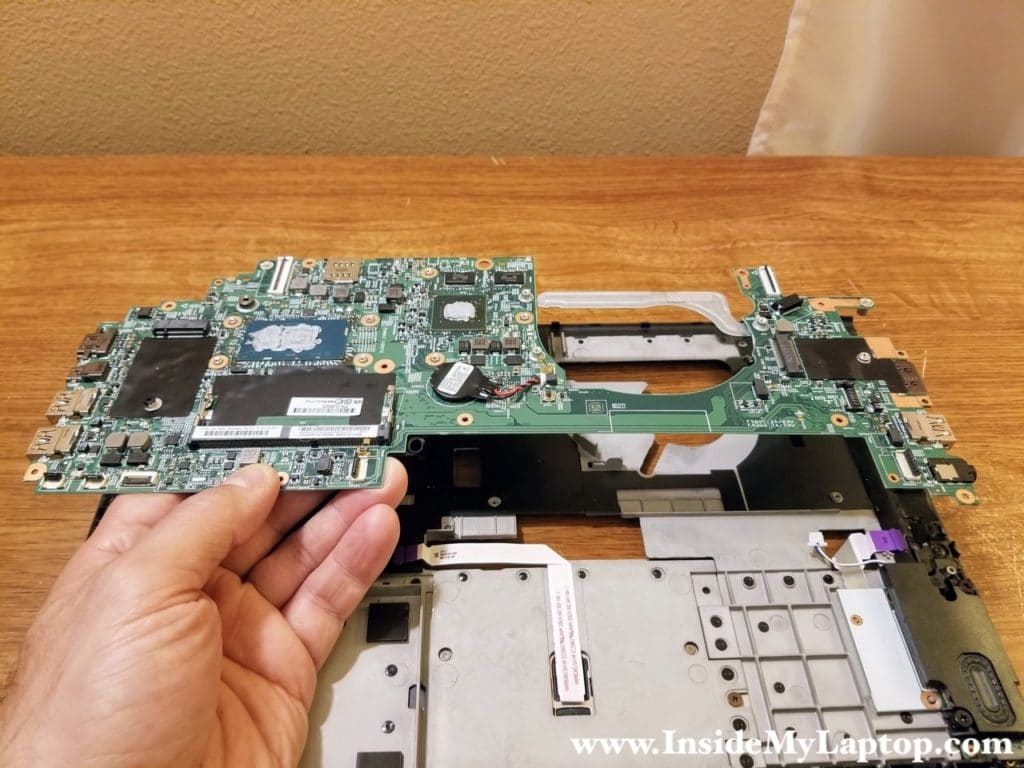
Here’s the other side of the motherboard.

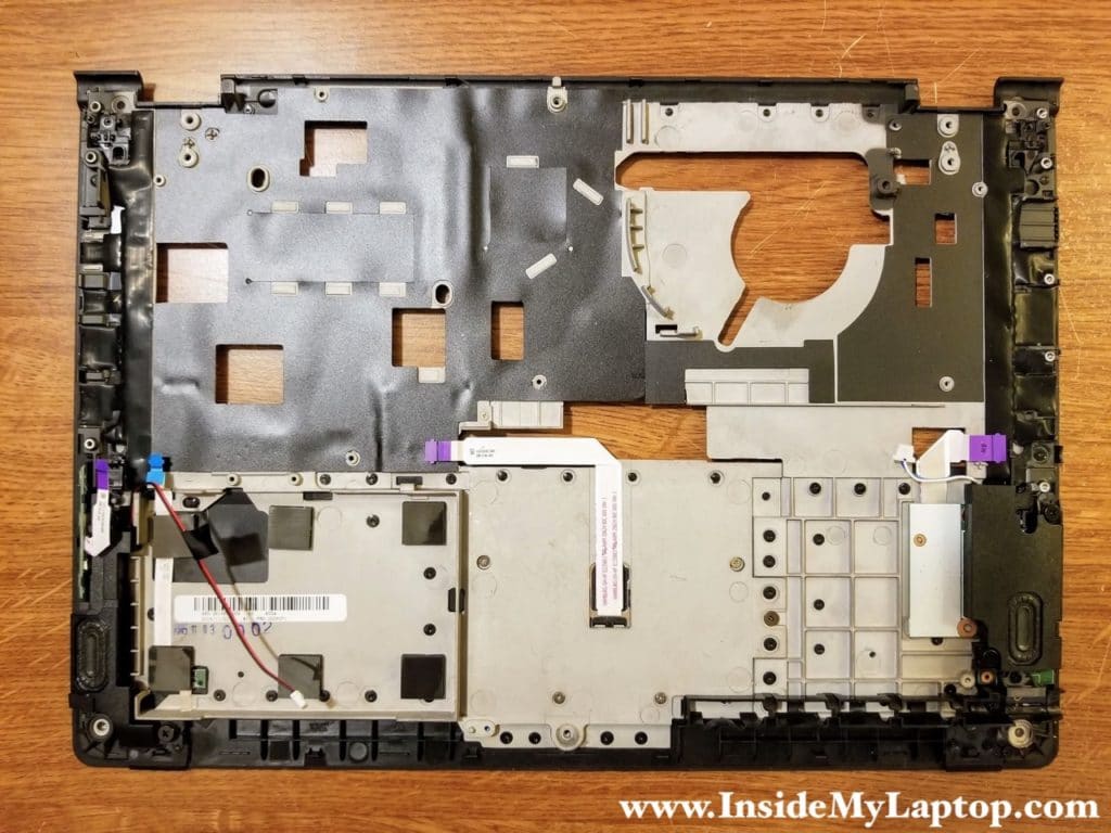
Here’s the top case with the motherboard removed.
