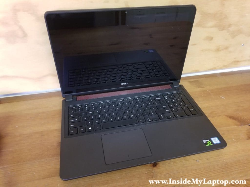
In this guide I will be taking apart a Dell Inspiron 15 7000 series gaming laptop.
I have Dell Inspiron 15-7559 model as an example but all teardown steps should be the same for Inspiron 15-7557.
- Hard drive, SSD, battery removal – STEPS 1-3.
- Keyboard and top case removal STEPS 4-10.
- Cooling fans and display removal STEPS 11-14.
- Wi-Fi card, DC power jack and motherboard removal STEPS 15-18.
STEP 1.
Loosen one screw securing the bottom cover and remove it from the laptop.
It may be necessary to apply some reasonable force to separate the cover from the case.

STEP 2.
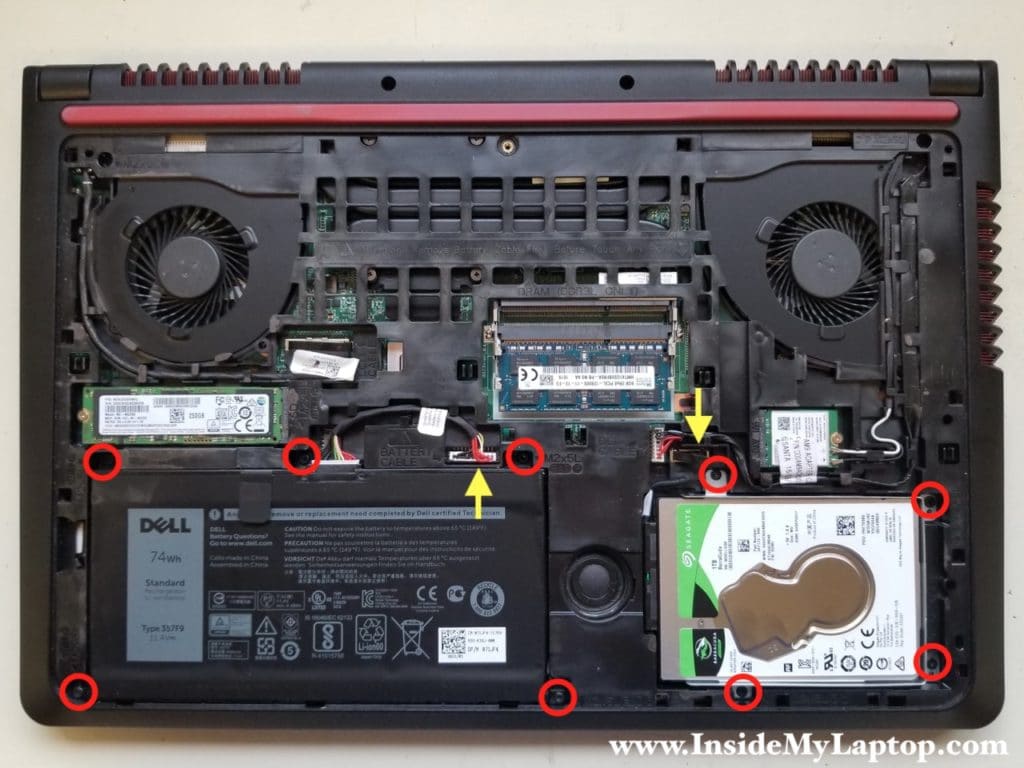
Under the cover you can access to the battery, both memory slots and both storage devices (SSD and 2.5″ hard drive).
Disconnect the battery cable from the motherboard and remove six torx T8 screws securing it to the case. Remove the battery. Replacement battery model 357F9.
Remove four screws securing the 2.5″ hard drive caddy. Unplug the hard drive cable from the motherboard. Remove the hard drive.
Installing a 2.5″ SATA solid state drive instead of the regular hard drive will improve laptop performance.
STEP 3.
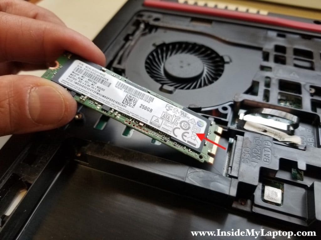
The solid state drive secured to the case by one screw.
Remove the screw and pull the SSD out of the socket. This is m.2 SATA III solid state drive.
STEP 4.
The keyboard is secured to the top case by five latches.
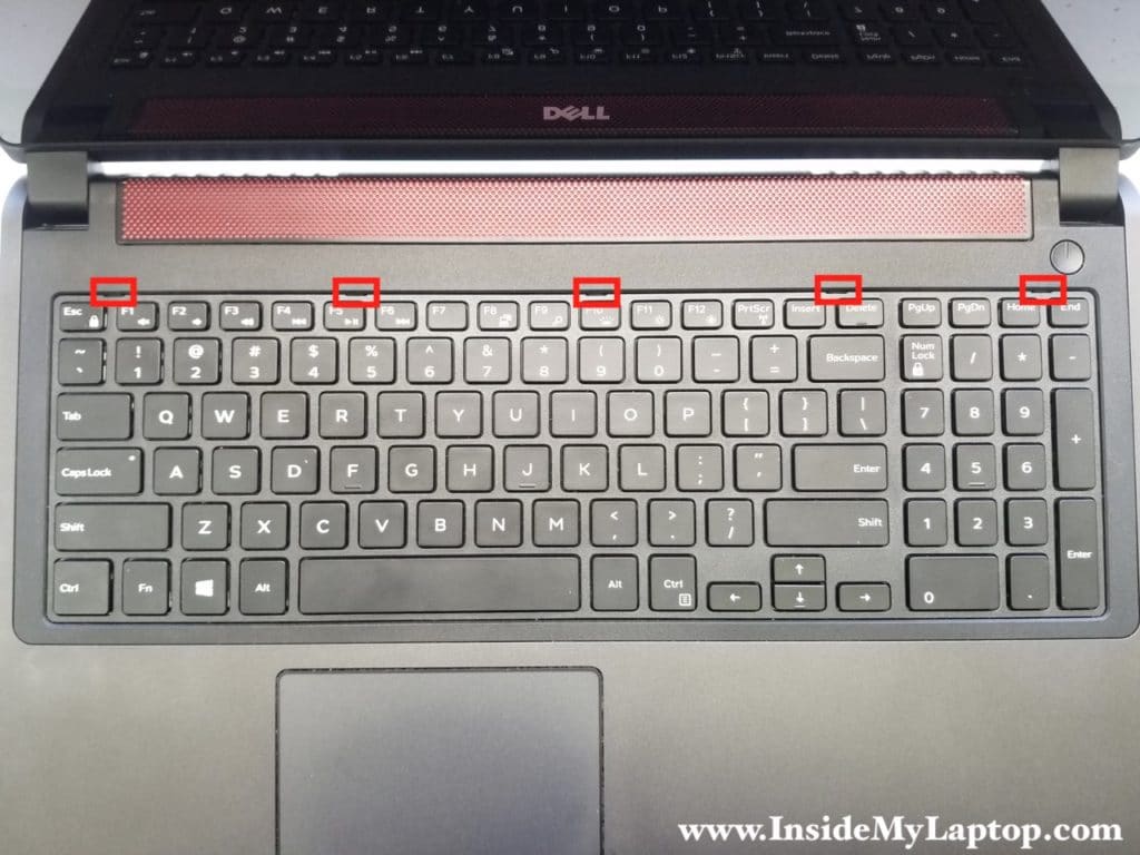
Using a thin metal case opener (or any other similar tool) push the latch inside the case. The direction is shown by the red arrow.
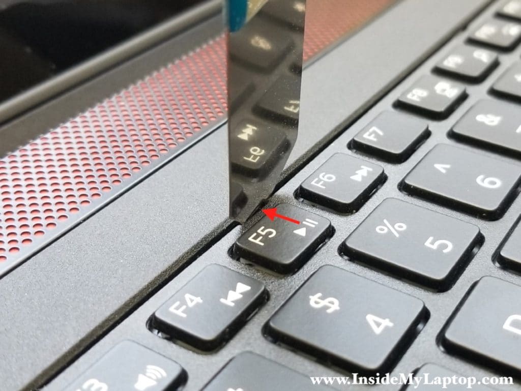
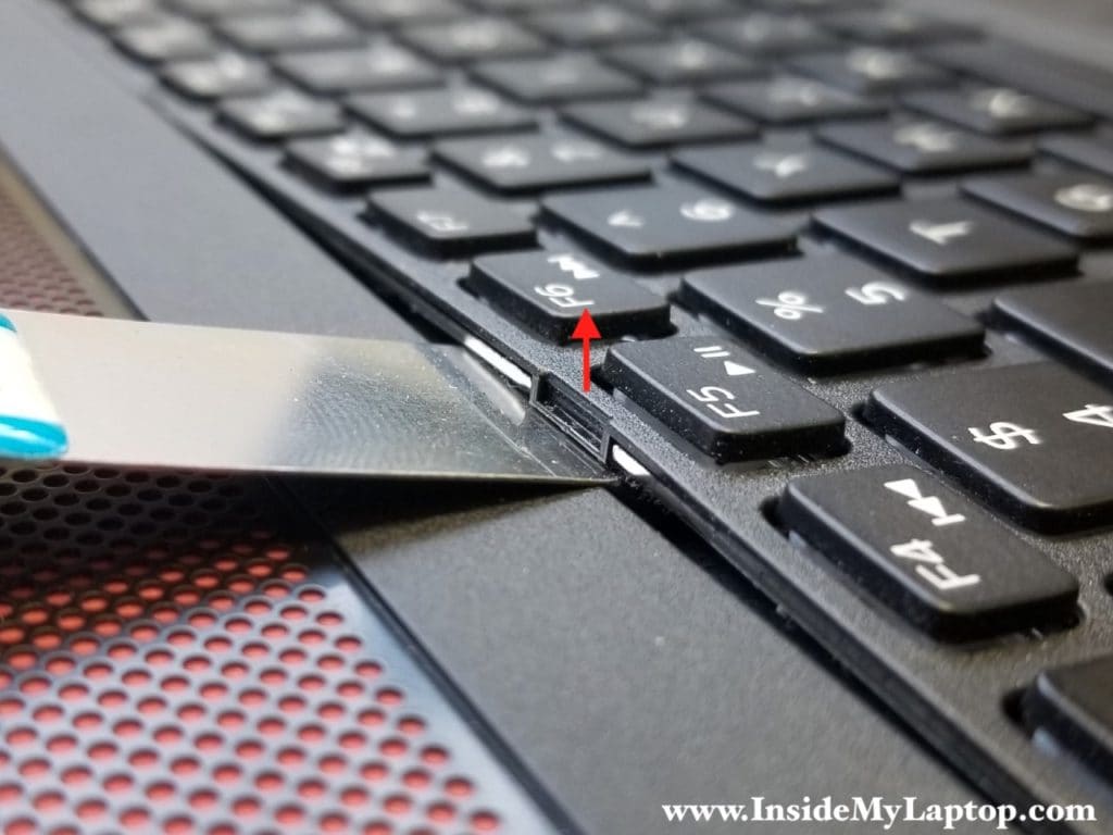
When the latch is moved inside the case, insert the case opener under the keyboard and lift it up.
Repeat these steps for all five lathes to separate the uppers side of the keyboard from the top case.
STEP 5.
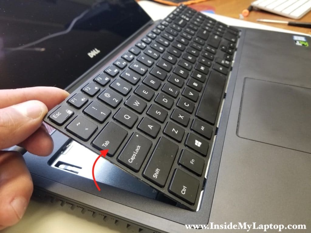
Continue separating the keyboard from the top case.
It may be necessary to apply some reasonable force to separate the keyboard.
STEP 6.
Move the keyboard towards the display assembly to get an access to the cables underneath.
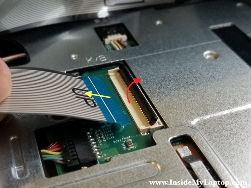
Disconnect the keyboard data cable (wide) and the keyboard backlight cable (narrow).
Do you see the “Up” sign on both cables? That’s how you insert them back onto the connectors during the re-assembly process.
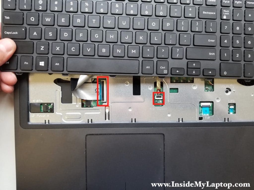
Here’s how to unlock both connectors. Lift up the locking tab so it opens up at a 90 degree angle. Pull the cable out of the connector.
STEP 7.
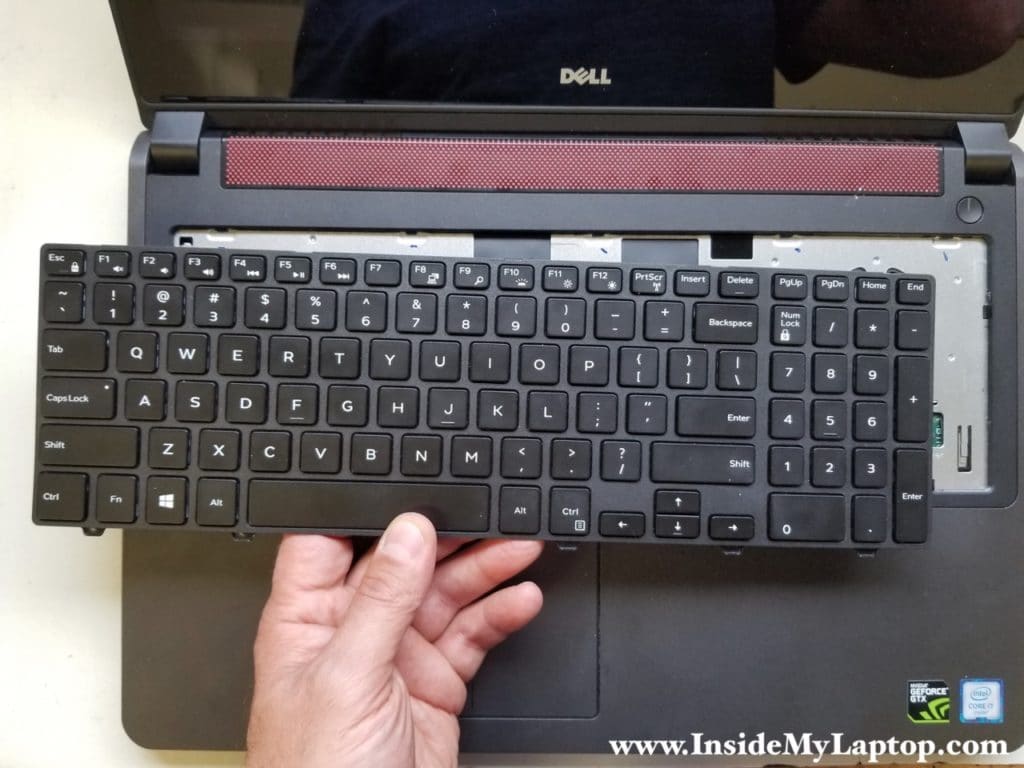
Remove the keyboard.
STEP 8.
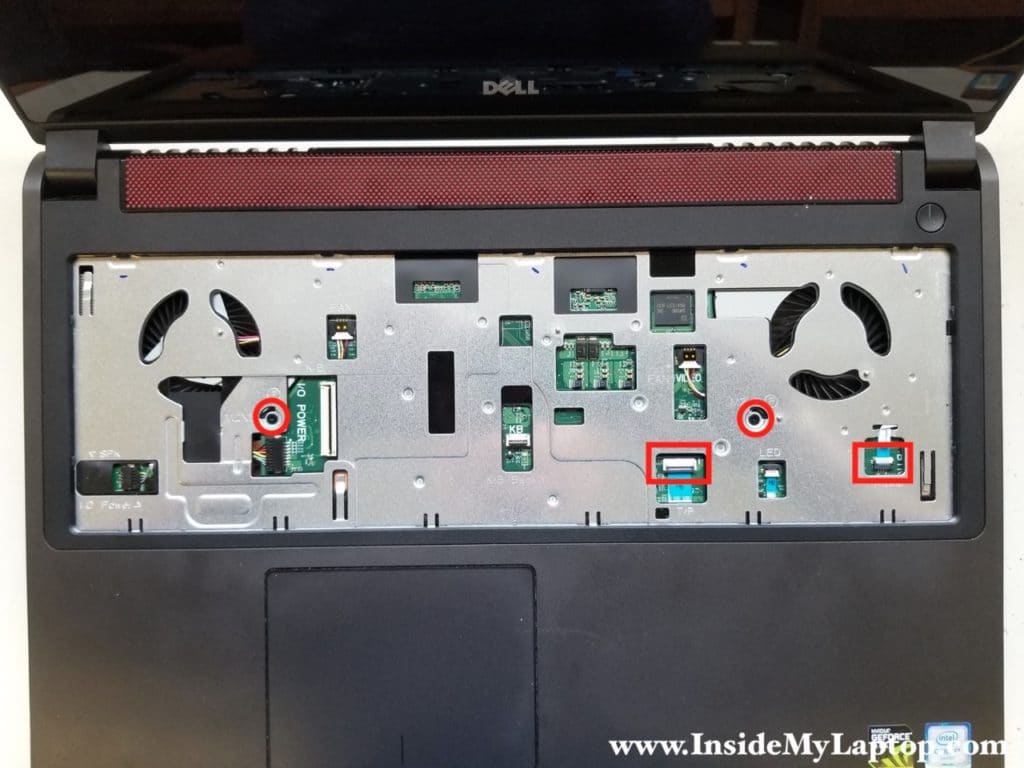
Remove two screws securing the top case.
Disconnect the touchpad cable (wide) and the power button cable (narrow).
STEP 9.
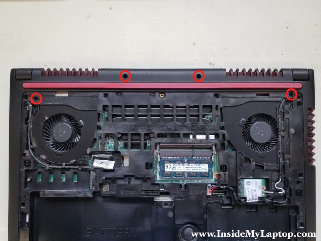
Remove four screws securing the top case to the bottom frame.
STEP 10.
Using a thin plastic case opener (or any other similar tool) start separating the top case from the bottom.
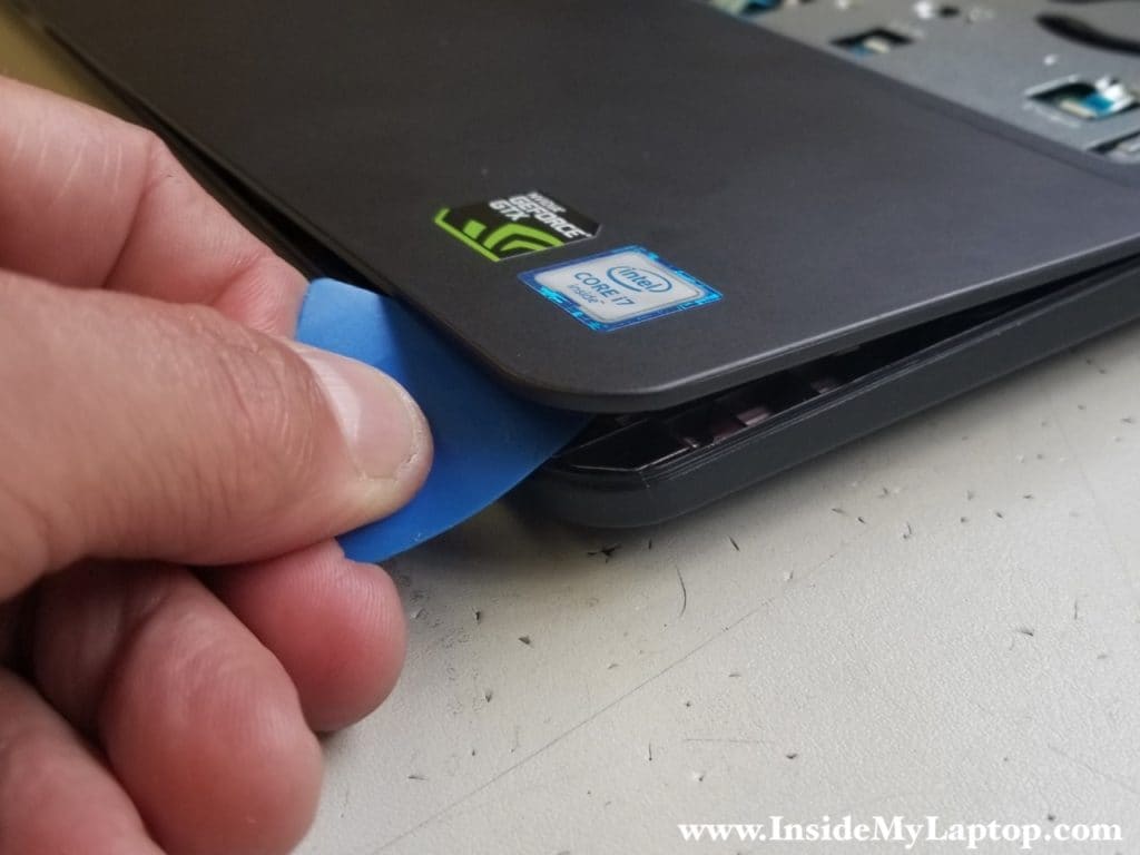
Continue removing the top case. If it’s getting stuck on the back, use the case opener to crack the case.
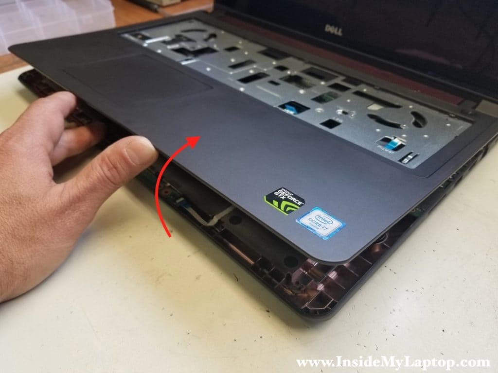
Remove the top case assembly.
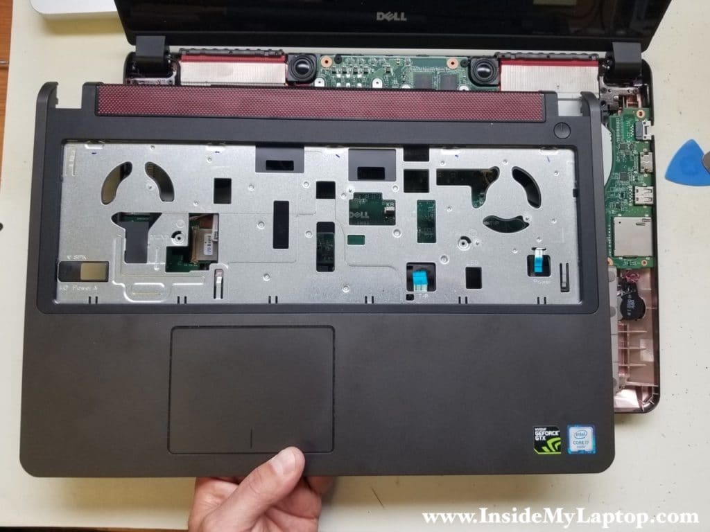
On the other side you can get access to the touchpad and the power button board.

‘
STEP 11.
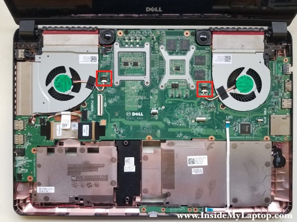
Dell Inspiron 15 7000 series laptop has two cooling fans installed.
Disconnect both fan cables from the motherboard. Remove both fans (there are no screws securing them).
STEP 12.
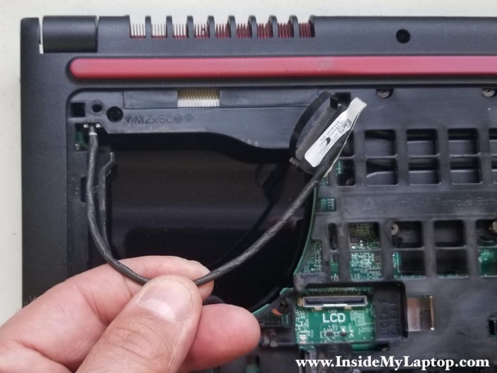
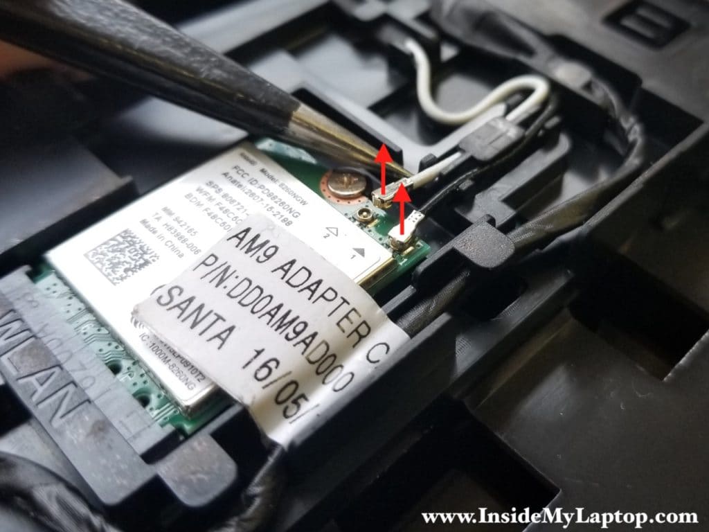
Now turn the laptop upside down to disconnect the display video cable and Wi-Fi antenna cables.
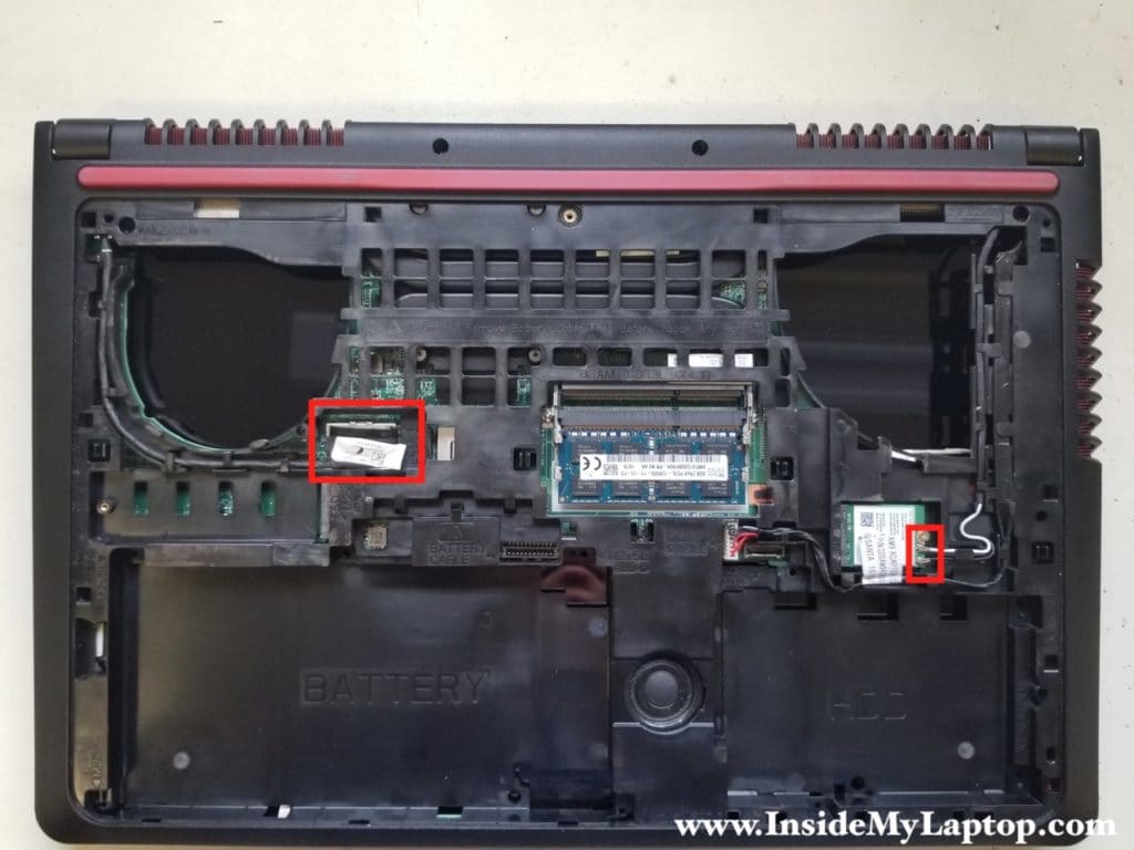
Unplug the display video cable (left rectangular) from the motherboard and unroute it from the guided path on the frame.
Disconnect both Wi-Fi antennas from the wireless card.
Unroute Wi-Fi antennas from the guided path on the frame.

STEP 13.
Remove four screws securing the display hinges (two screws per hinge).
By the way, this model has a pretty common hinge separating problem.

STEP 14.
Separate the display assembly from the base and remove it.
In the next post I explain how to take apart the touch screen display in order to remove and replace failed video cable.
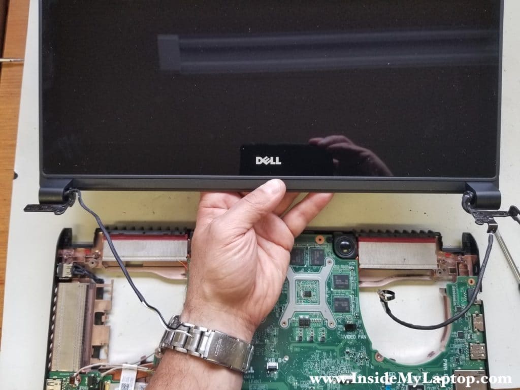
STEP 15.
Remove one screw securing the wireless card and pull the card out of the socket.

STEP 16.
Disconnect the DC jack harness from the motherboard.
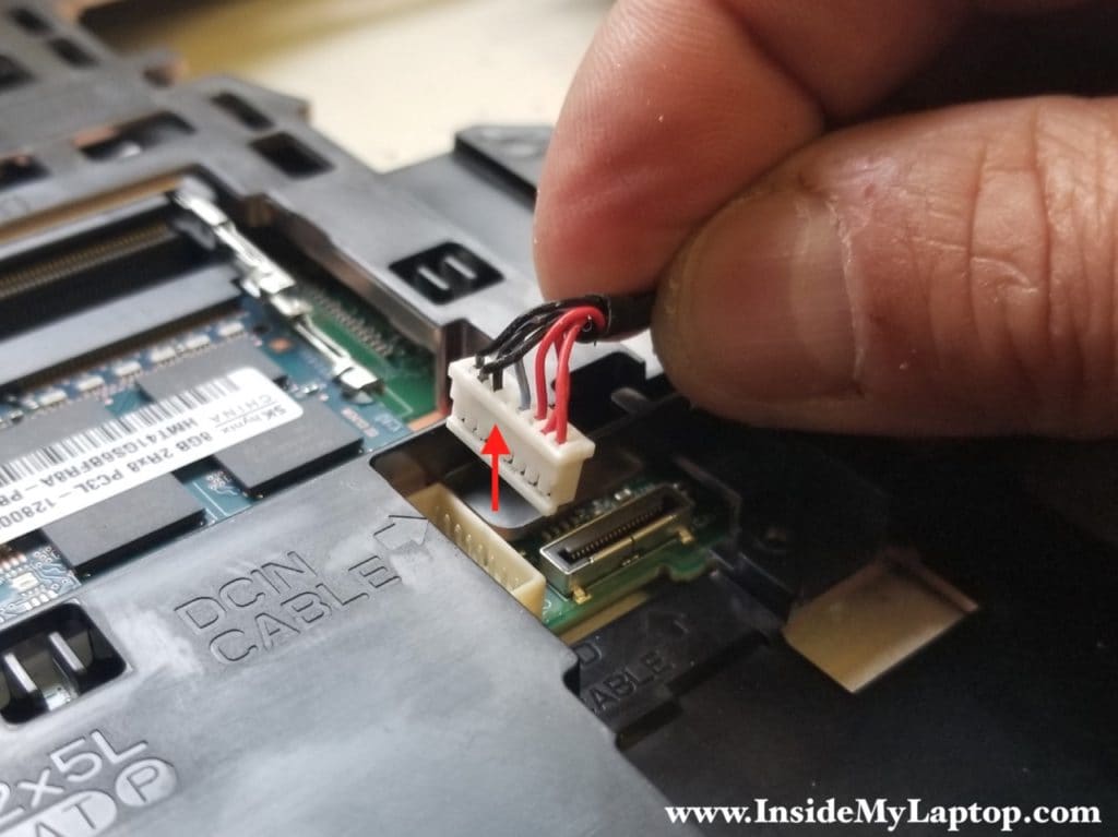
Unroute the DC jack harness from the guided path on the frame.

Remove the DC jack.
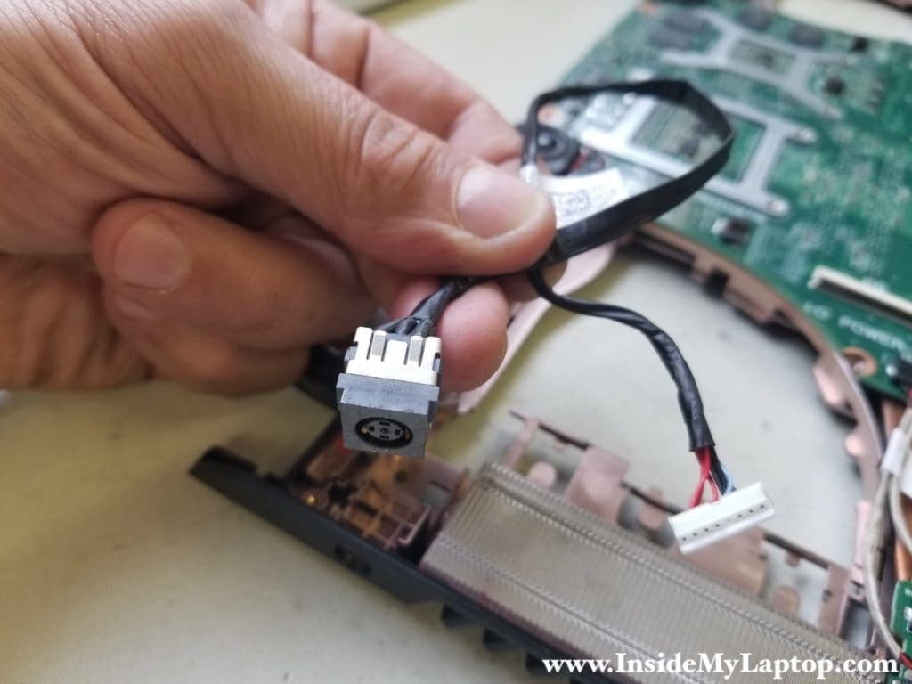
STEP 17.
Disconnect all cables from the I/O USB audio board (from top to bottom):
- I/O board power cable
- I/O board data cable
- Speaker cable

The data cable is locked by a metal clip.
First, lift up the metal clip (red arrow). Second, pull the cable out of the connector.
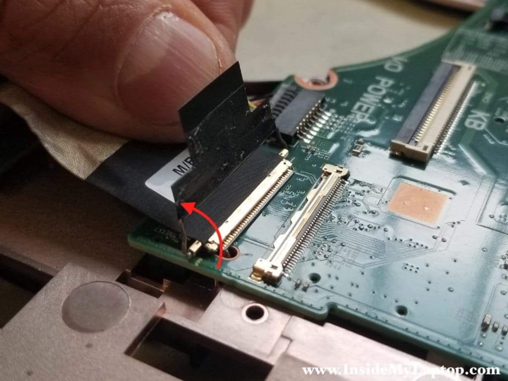
There is a small plastic hook securing the I/O USB audio board to the frame.
Push on the hook to release the board.
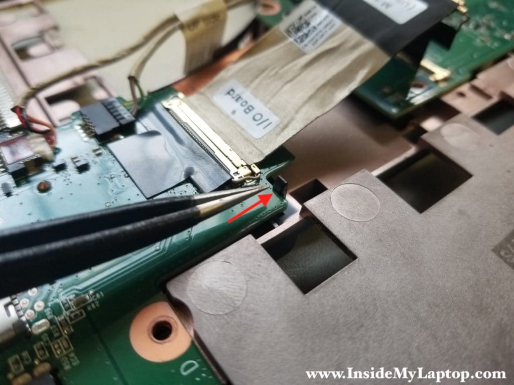
Remove the I/O USB audio board.

STEP 18.
Disconnect the status LED board cable from the motherboard (red square).
Disconnect the CMOS battery (red arrow). The connector is hidden on the bottom side of the motherboard but it’s easily accessible.
There is a small plastic hook securing the motherboard to the frame. Push on the hook (yellow arrow) to release the motherboard.

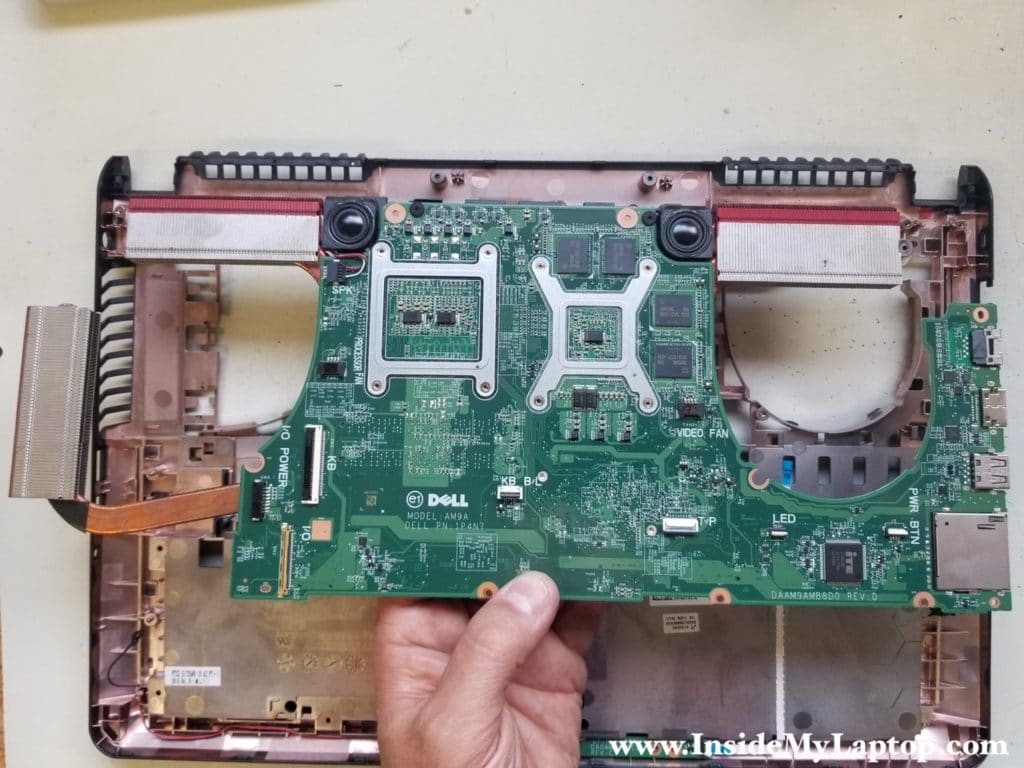
Remove the motherboard from the frame.
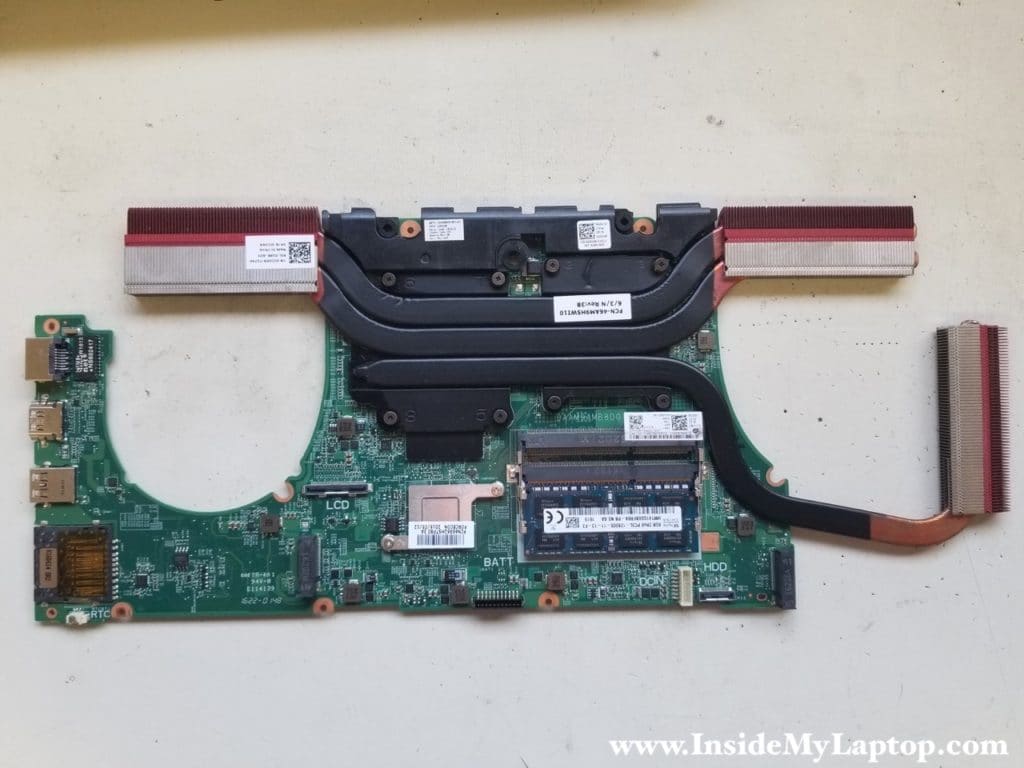
Here’s a picture of the other side of the Dell Inspiron 15 7000 series (7559 7557) motherboard.
Now you can remove the heatsink and reapply thermal grease (if necessary).
Matt
I have a problem with my Inspiron 5577. The left side of the display separates from the bottom case. When I move the display, there is a gap between the display and bottom.
Do you know what is wrong? Is it a hinge problem? Can I use this guide to fix my laptop?
IML Tech
@ Matt,
Most likely it’s not a hinge related problem. It’s related to the bottom case.
There are only two screws securing each display hinge to the bottom case as you can see in the step 13. I think in your case both screw anchors got pulled out of the bottom case. I think it will be a pretty common problem with the Inspiron 5000/7000 series laptops because the display is pretty heavy and two screws per hinge is not enough to support it.
You will have to replace the bottom case. Basically you’ll have to go through all disassembly steps.
I believe that Inspiron 5577 has the same (or very similar) design so my guide should work.
Here’s the bottom case part number: 08FGMW
Patricia C
Thanks for the instructions! One of the fans started making lots of noise last week. I’ll attempt replacing it myself. The fan noise drives me crazy!
Marche
Hi, I wonder if the red accents can be modded? I’d like to change the colour on every single one of them, make a less gamey machine.
Lubos Nosek
Hi there, do u still own this laptop ? I would need to see cabling on the power jack side if it is possible. I have broke the jack wires and i dont have an idea about wiring. You have the jack on the photo from the front side and i would need to check the backside for the wire diagram with colors.
Thanks in advance
rexzone
Where is the reed / lid switch located? Is that what happens if I leave the screen open, the screen does not turn on, if it closes it and I open it, it just works, and then I open it all, it works fine but I can’t find the piece that you see if the lid is below or above
IML Tech
@ rexzone,
I’m not sure where the lid close switch is located on this particular model but most likely it’s a magnetic switch. Use a small magnet. Move the magnet along the perimeter of the display and palmrest assembly. The location of the lid close switch will be at the place where your magnet sticks to the display or palmrest.
Danillo
Very insightful guide. Thank you very much!
My laptop screen has not been working properly. The image shown is so dark that I can barely see it. Thanks to a secondary monitor I was able to complete my tasks. I tried changing the screen flat cable and nothing has changed.
Doing some research I found there is a slight possibility of being a blown fuse. Do you have any idea how I can manage to find the screen fuse in the motherboard?
Thanks in advance!
IML Tech
Danillo, I don’t fix PC motherboards on the component level and don’t know the location of the fuse. In order to find the backlight fuse you’ll have to have the motherboard schematics.
From my experience, if the screen backlight goes off, most likely there is a problem with the LCD screen itself or the display cable. You’ve replaced the display cable already so the screen is the next.
Danillo
I see. Sorry to bother you. Do you know how I can find the schematics? I saw there are some codes beside every component but I struggled to find it (I’m not a hardware technician nor English native speaker lol).
IML Tech
I’m not sure if this is any help but here’s what I found: https://bit.ly/372J3fz
It has QUANTA AM9A MOTHERBOARD SCHEMATIC DIAGRAM. I think you you need full schematics with the board-view, you’ll need to search on google and buy them. Usually they are not free.