In this guide I will be taking apart an Alienware 17 R4 (model P31) laptop.
This laptop has many different types of screws installed. Keep track of all removed screws and stay organized.
Repair tools I used during the disassembly process: Phillips screwdriver #0, case opener tool, tweezers.
STEP 1.
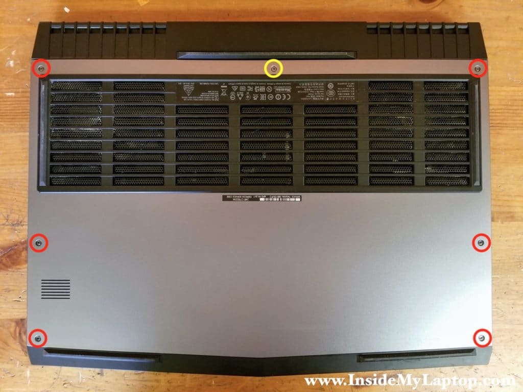
Remove six screws securing the bottom cover (color-coded in red).
Loosen one captive screw (yellow). It will stay attached to the cover.
STEP 2.
Start separating the bottom cover from the rest of the laptop.
Remove the bottom cover.

STEP 3.
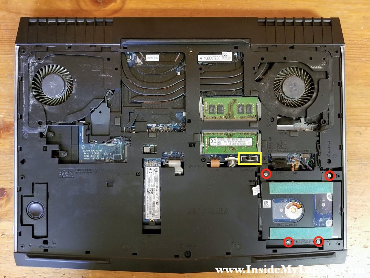
Disconnect the battery cable before proceeding with any further laptop disassembly.
The battery cable connector located just above the 2.5 hard drive bay.

STEP 4.
Remove four screws securing the 2.5″ hard drive bracket.
Disconnect the hard drive cable from the motherboard (yellow).
There is a black belt on the top of the connector. Just pull it up to unplug the connector from the motherboard.
STEP 5.
Remove the 2.5″ hard drive assembly with the cable attached to it. You can install a 2.5″ solid state drive instead of this regular hard drive.
Both RAM slots accessible here. Alienware 17 R4 supports up to 32GB DDR4 2400/2666/3200 SODIMM RAM modules.

STEP 6.
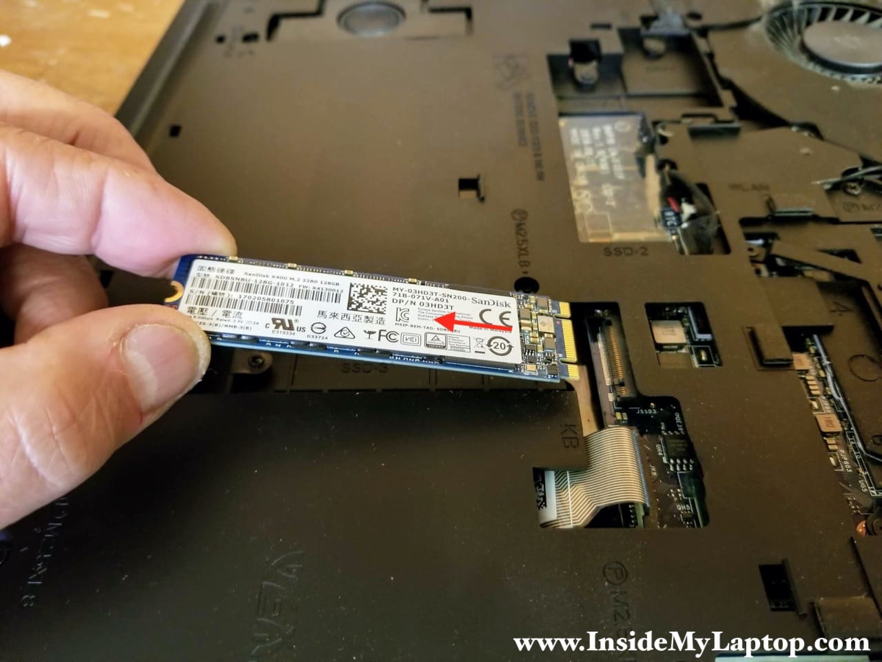
Remove one screw securing the solid state drive.
Pull the SSD out of the slot.
This laptop has a 128GB m.2 SATA SSD installed but I believe it supports NVMe solid state drives and they are much faster.
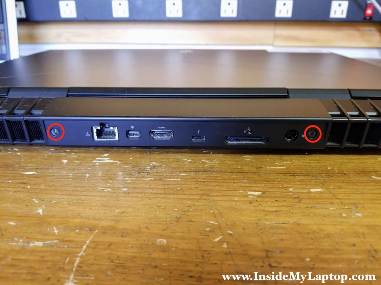
STEP 7.
Remove two screws from the rear ports cover.
STEP 8.
Remove the rear ports cover. You’ll have to wiggle the cover to disengage hidden latches securing it. Also, using a small flat-head screwdriver might help to separate the cover from the laptop.

STEP 9.
Remove one screw securing the wireless card.

STEP 10.
Lift up the wireless card a little bit and remove the clear plastic cover.
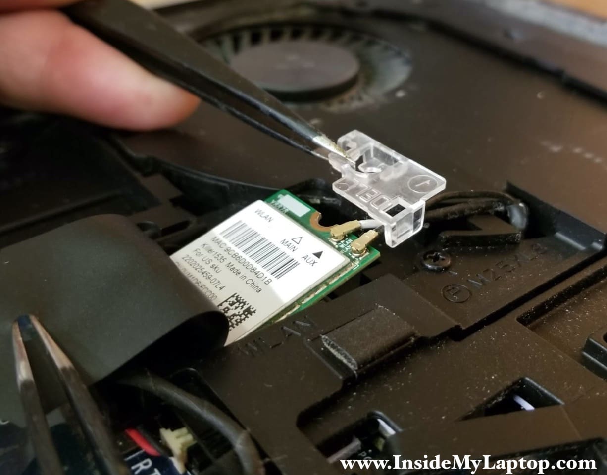
STEP 11.
Unplug both wireless antenna cables (red arrows) and pull the wireless card out (orange arrow).

STEP 12.
Remove all screws from the computer base. Two silver screws color-coded in green are shorter than other fourteen screws color-coded in red.
Disconnect two tron-light cables (yellow) from the motherboard.

Here’s how to disconnect the tron-light cable. Simply lift up and unplug the connector from the motherboard.

STEP 13.
Start separating the computer base from the rest of the laptop.

Continue removing the computer base as it shown on the following picture.

STEP 14.
Remove the computer base completely.

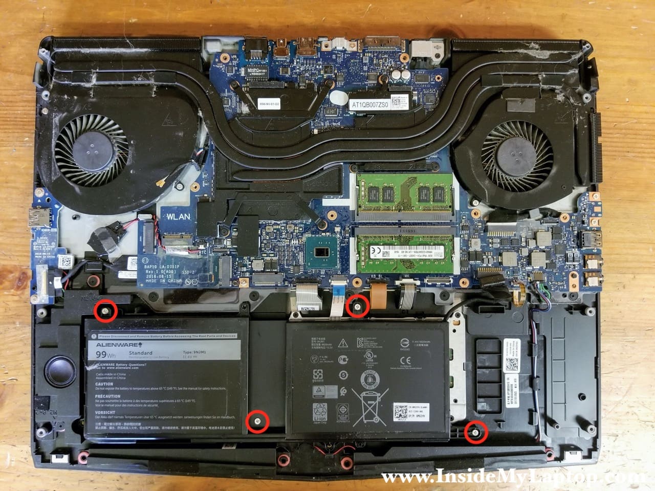
STEP 15.
Remove four screws securing the battery.
As you remember, we already disconnected the battery cable in the step 3.
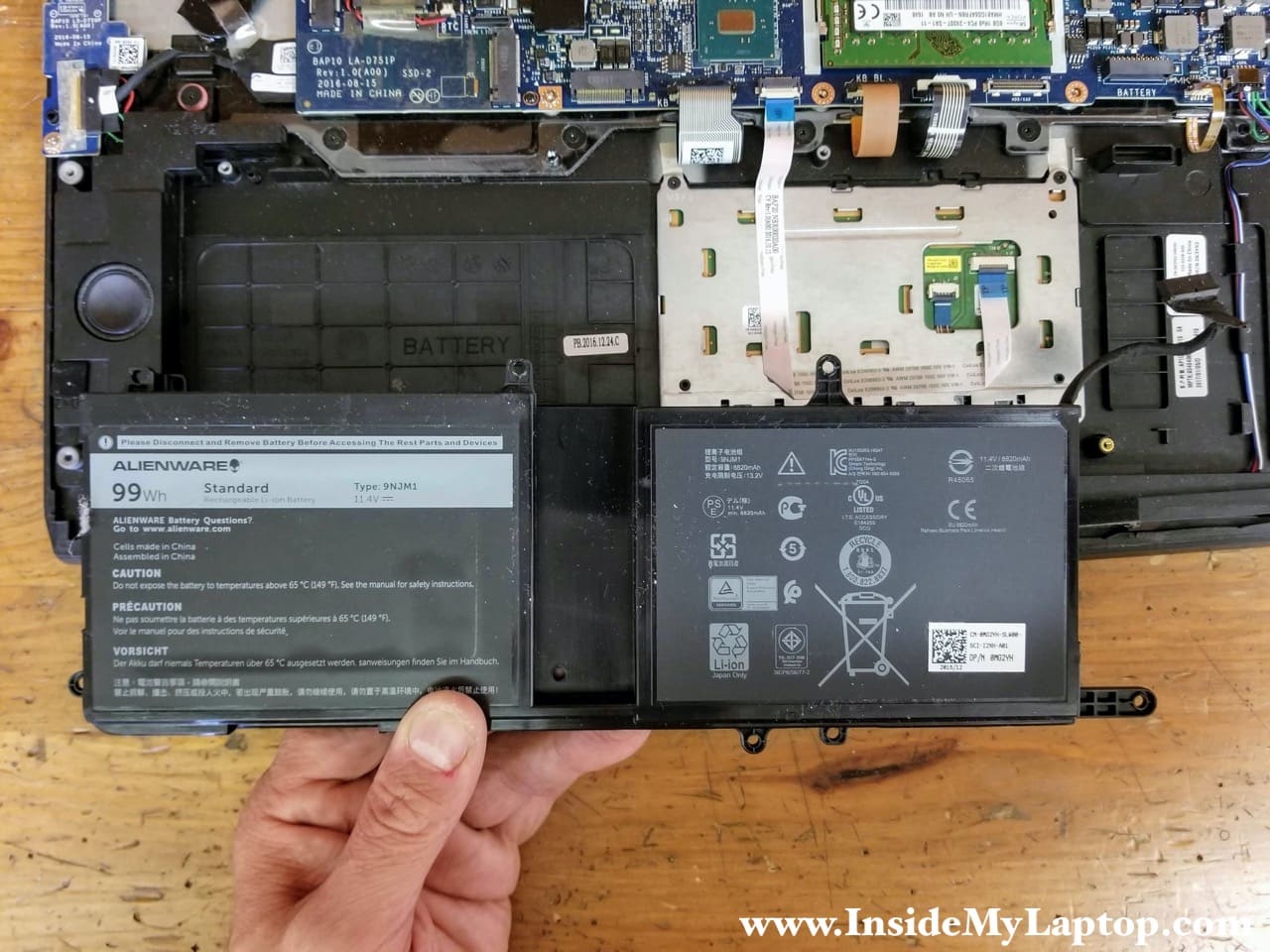
STEP 16.
Lift up and remove the battery.
Alienware 17 R4 (model P31E) battery type: 9NJM1.
STEP 17.
Disconnect all following cables located on the rear side.
– Tobii eye-tracker cable (red).
– Power button board cable (orange).
– Display cable (green).

In order to disconnect the Tobii eye-tracker cable simply lift it up and unplug from the motherboard.

The power button board cable can be removed after you unlock the connector.
In order to unlock the connector slide the brown locking tab in the shown direction (two red arrows).

Lift up the metal bracket (red arrow) to unlock the display cable connector. Pull the display cable out (yellow arrow).
STEP 18.
Remove four screws (red) securing the motherboard and four screws (orange) securing both cooling fans. Disconnect all cables from the motherboard.
I will leave the RTC battery connected to the motherboard. You can remove it if necessary.
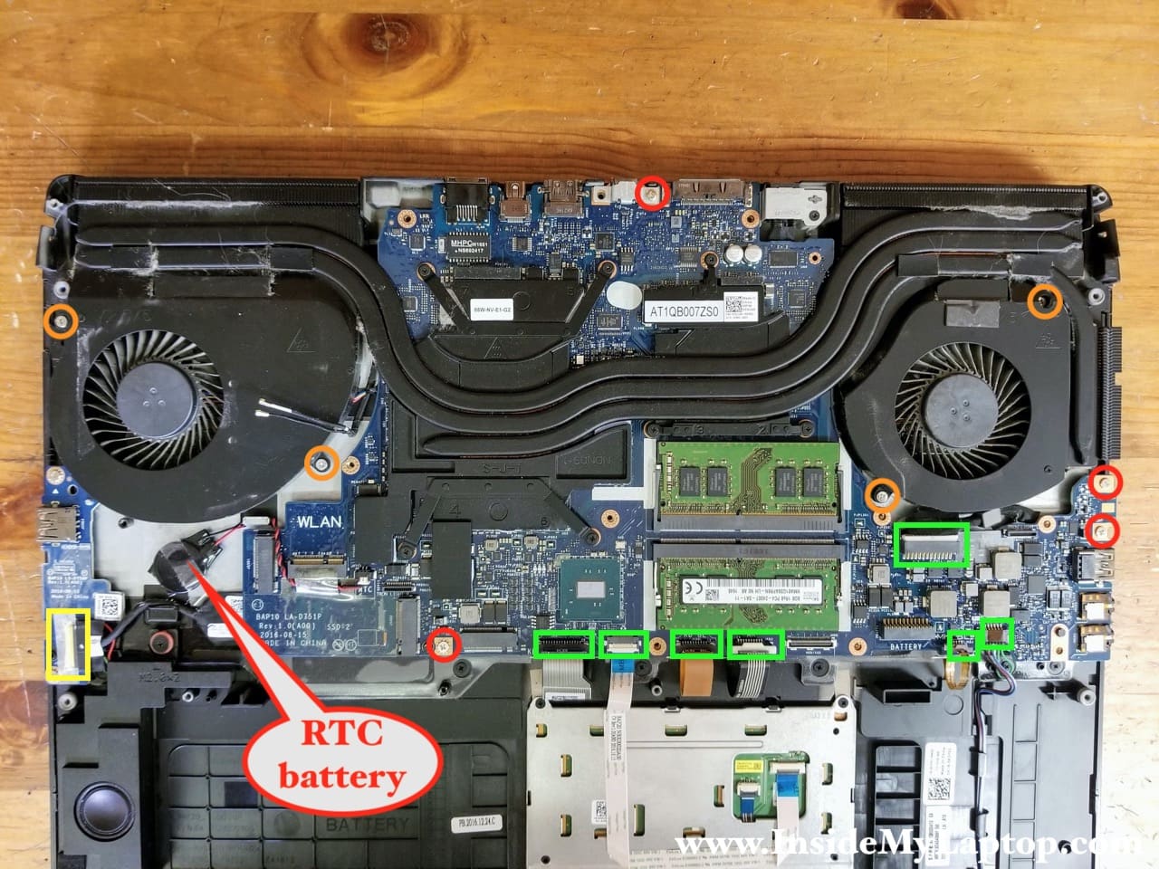
There is a meta cover securing the USB-C connector. Remove the cover.

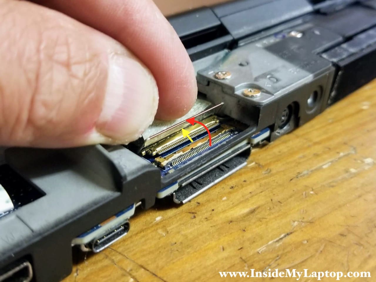
Here’s how to disconnect cables plugged in into vertical connectors.
Unlock the connector by moving the locking tab in the shown direction (red arrows).
Pull the cable out (yellow arrow).

Here’s how to disconnect the trackpad cable.
Lift up the locking tab to unlock the connector (red arrow) and pull the cable out.

Here’s how to disconnect the I/O board cable.
Unlock the cable by lifting up the metal bracket (red arrow) and after that pull the cable out.

STEP 19.
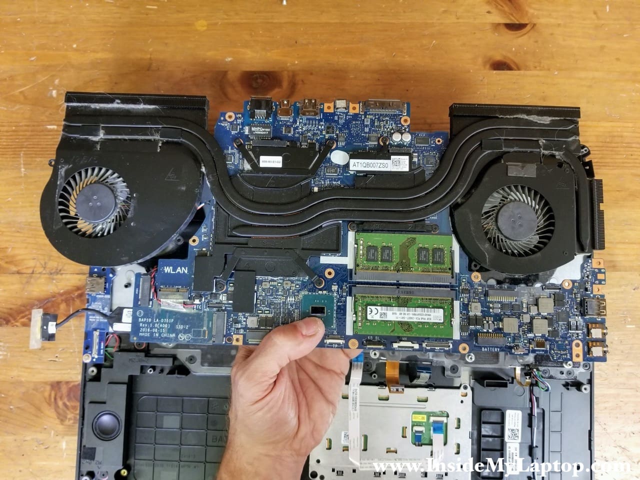
With all screws removed and cables disconnected you can start separating the motherboard from the palmrest assembly.

STEP 20.
Remove the motherboard.
I don’t show how to remove the heatsink/fan assembly but it’s very easy. There are a few screws securing the heatsink to the motherboard.
Here’s the other side of the motherboard.

In Alienware 17 R4 (model P31E) laptop the keyboard permanently attached to the palmrest and cannot be removed.

The power button board secured to the palmrest with two screws.

The DC power jack harness is taped to the palmrest assembly.
