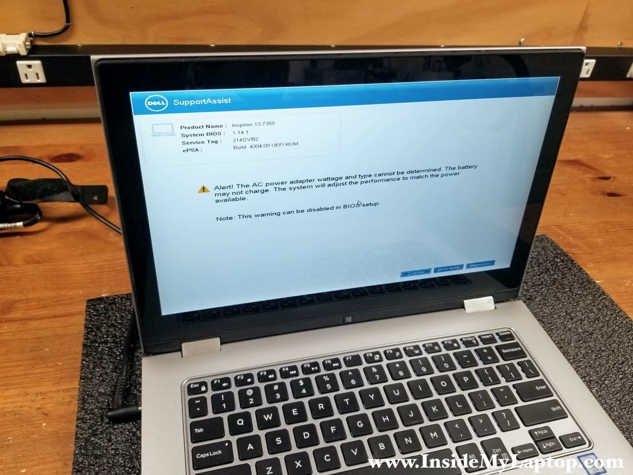
In this guide I will be replacing the touchscreen on a Dell Inspiron 13 7000 2-in 1 (model P57G) series laptop.
You can use this disassembly instructions for other models with the P57G body type, such as:
– Dell Inspiron 7347
– Dell Inspiron 7348
– Dell Inspiron 7352
– Dell Inspioron 7353
– Dell Inspiron 7359
and probably some some other models in the Inspiron 13 7000 series 2-in-1 computer line.
For the touchscreen replacement you will need just a few basic repair tools: Phillips #1 screwdriver, case opener tool and tweezers (optional).
According to the service manual, it is necessary to remove the display from the laptop in order to replace the touchscreen but I was able to replace it with the display still attached.
We’ll be replacing the touchscreen when the laptop folded in tablet mode as shown on the following picture. I would recommend disconnecting the battery from the motherboard before taking apart the display panel.

Removing the touchscreen
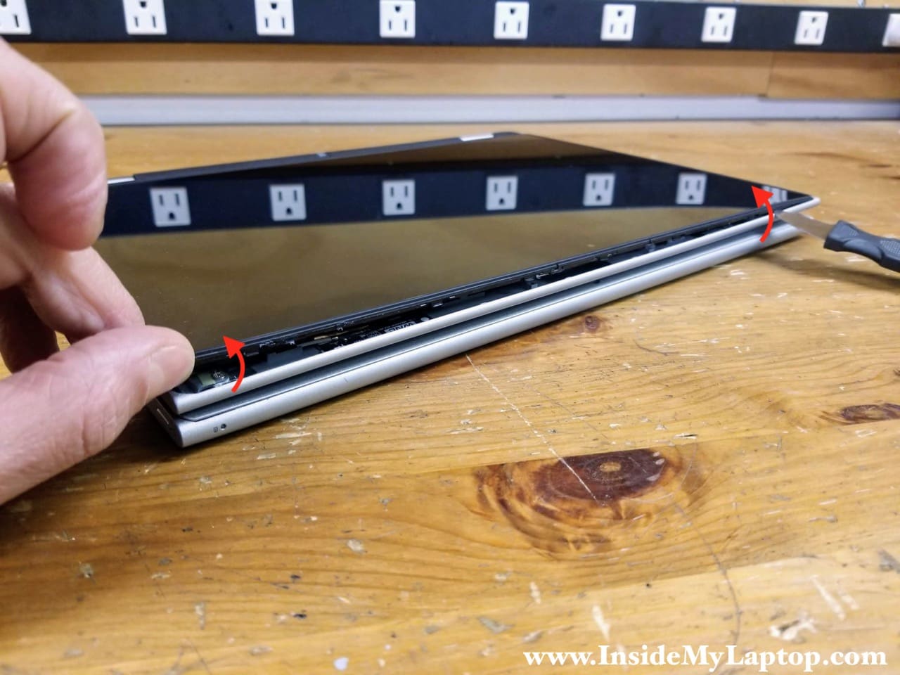
STEP 1.
Start separating the touchscreen assembly from the display back cover using a thin case opener tool. Pry up the touchscreen. There are multiple hidden latches securing the touchscreen to the back cover.

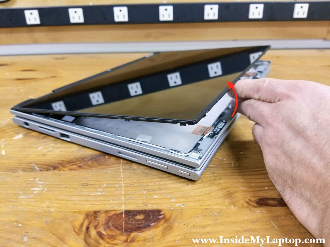
STEP 2.
Continue removing the touchscreen with your hands while helping yourself with the case opener tool.
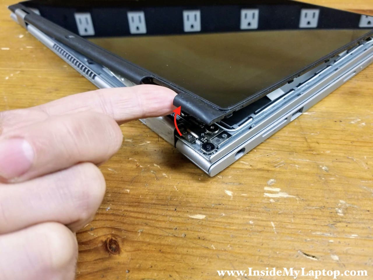
STEP 3.
When the touchscreen assembly separated on the top side of the display panel, move to the hinge area.
STEP 4.
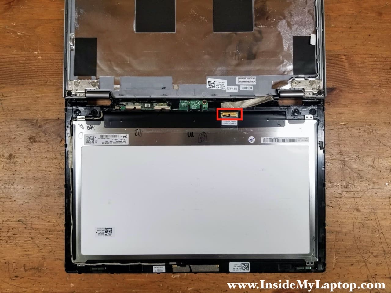
Continue removing the touchscreen assembly until it’s completely separated from the display back cover. Turn the touchscreen over and place it the front side down on the desk.
Now you can access all cables and board located on the back side. Let’s disconnect the video cable first.
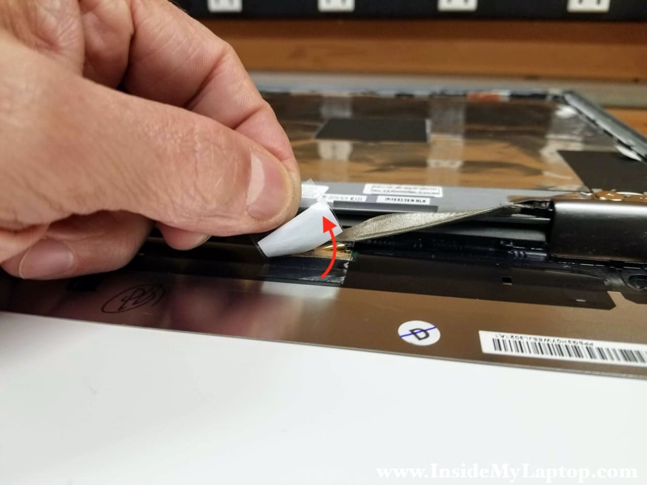
STEP 5.
Peel off the tape securing the video cable connector.
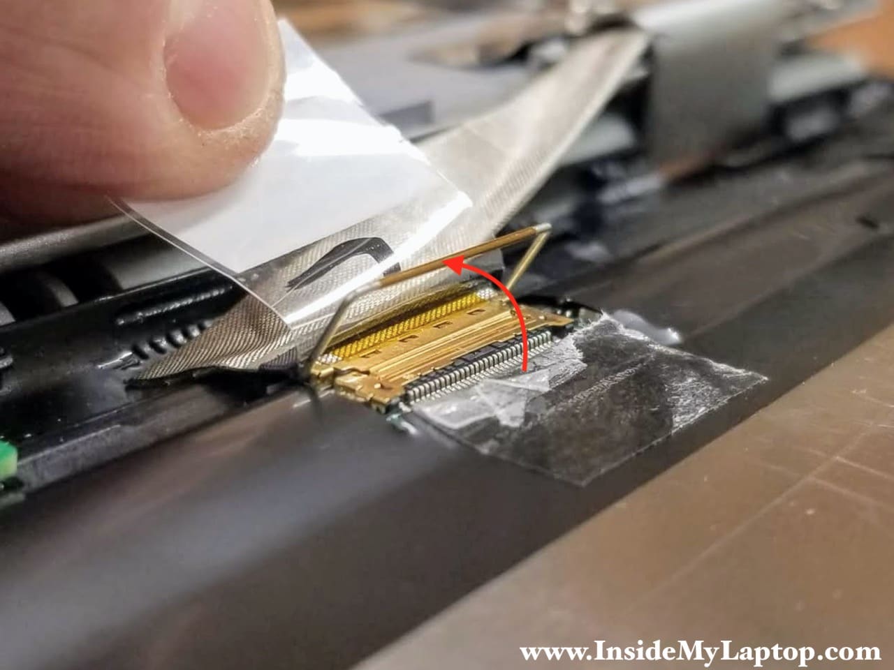
STEP 6.
Lift up the metal bracket to unlock the video cable connector.
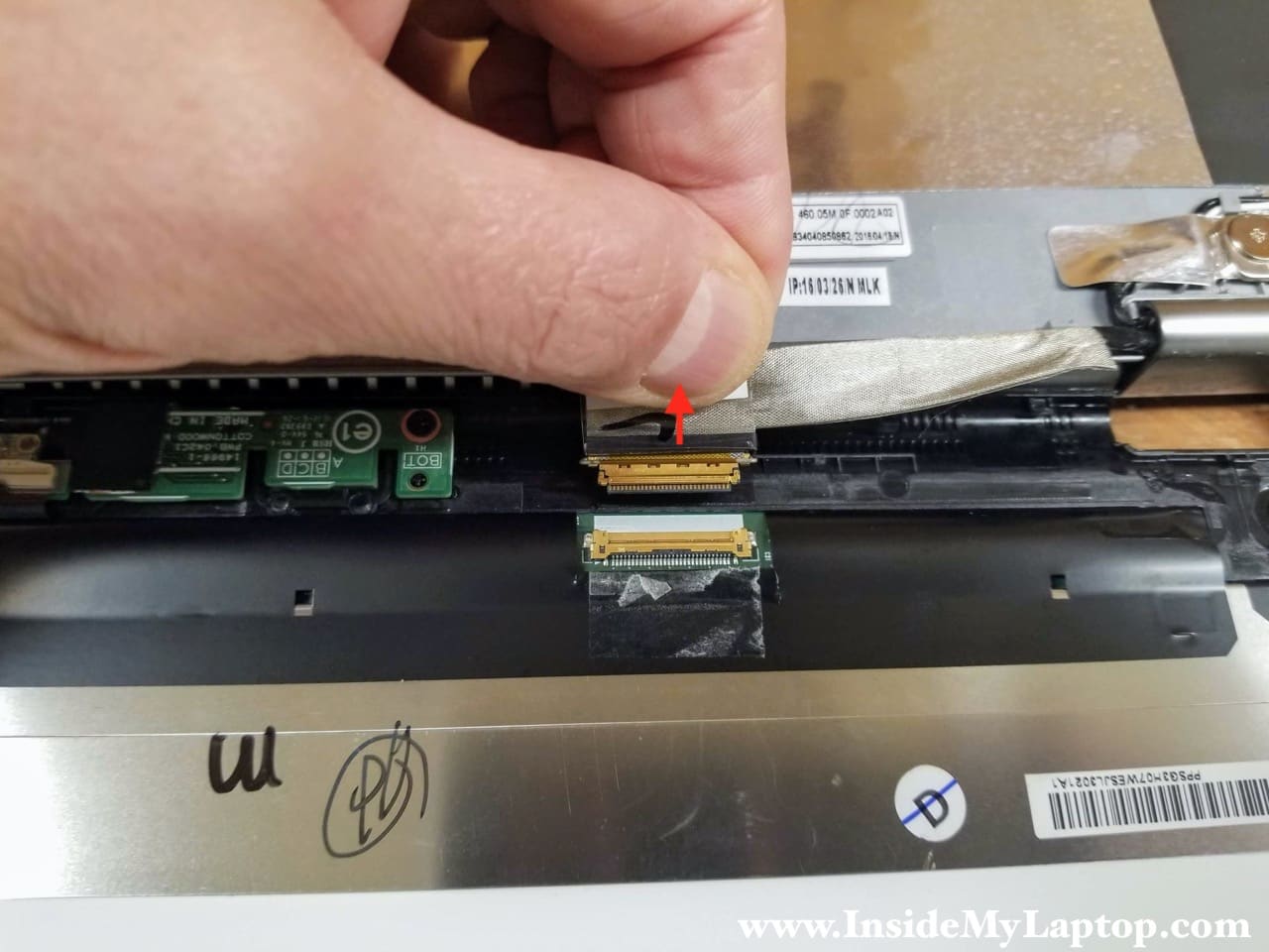
STEP 7.
Pull the video cable out of the connector on the back of the screen.
STEP 8.
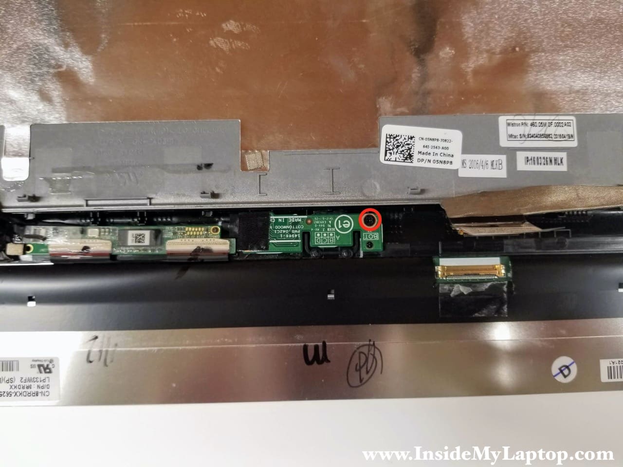
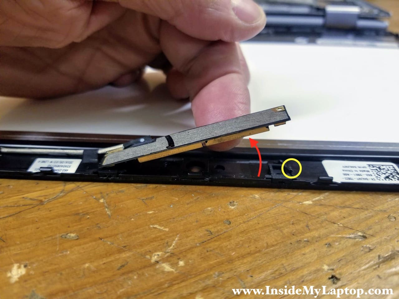
Remove one screw securing the Windows home button board.
STEP 9.
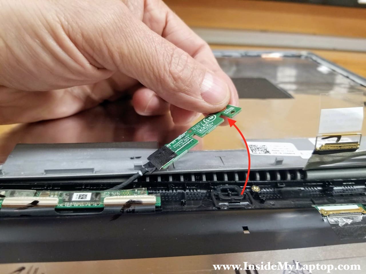
Separate the Windows home button board from the bezel and put it aside. Note that the cable is still connected to the board.
STEP 10.
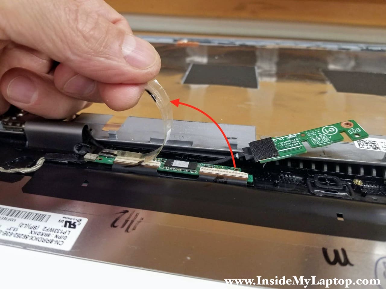
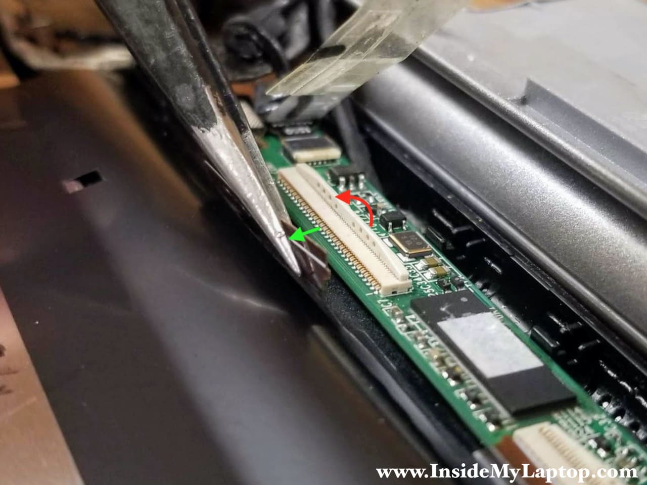
Peel off the clear tape securing the digitizer control board connectors.
STEP 11.
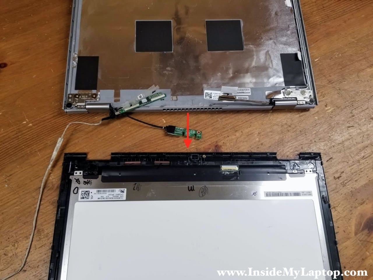
Disconnect both cables from the digitizer control board.
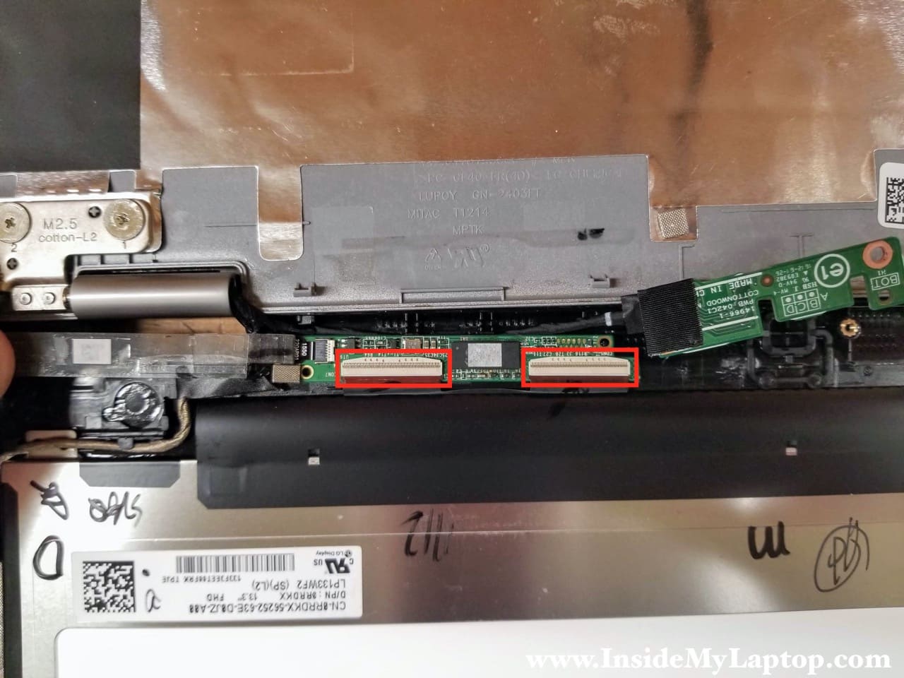
Lift up the locking tab at a 90 degree angle to unlock the connector (red arrow). Pull the cable out.
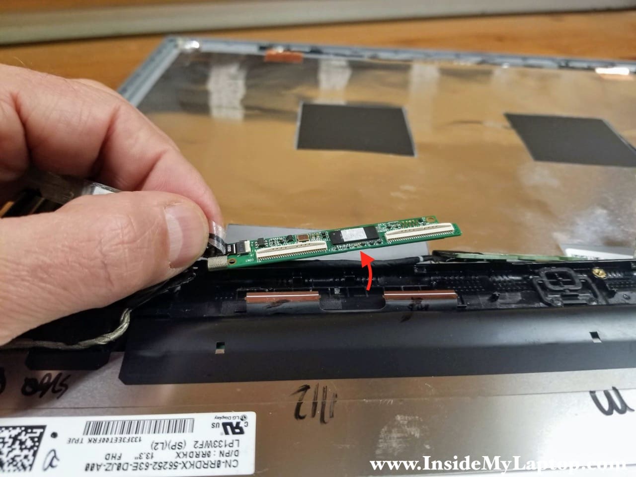
STEP 12.
Separate the digitizer control board from the bezel and put it aside. Note that there is a cable still connected to the left side of the board.
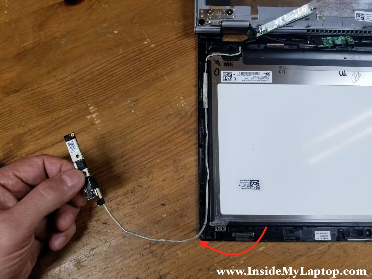
STEP 13.
Release the latch on the right side of the webcam board and separate the webcam board from the bezel.
STEP 14.
Un-route the webcam cable from the guided path on the side of the display assembly.
STEP 15.
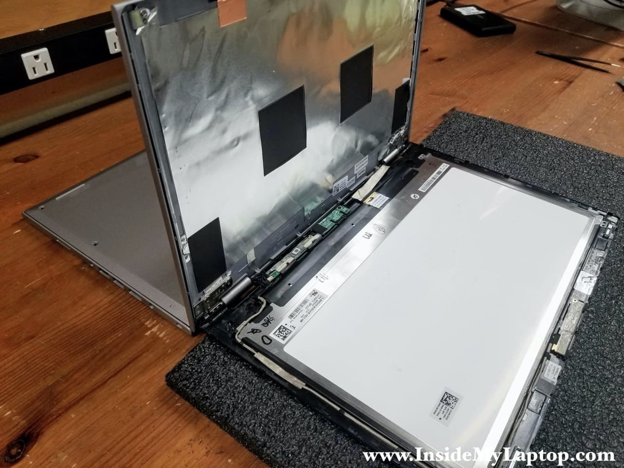
With all cables disconnected, you can remove the touchscreen completely.
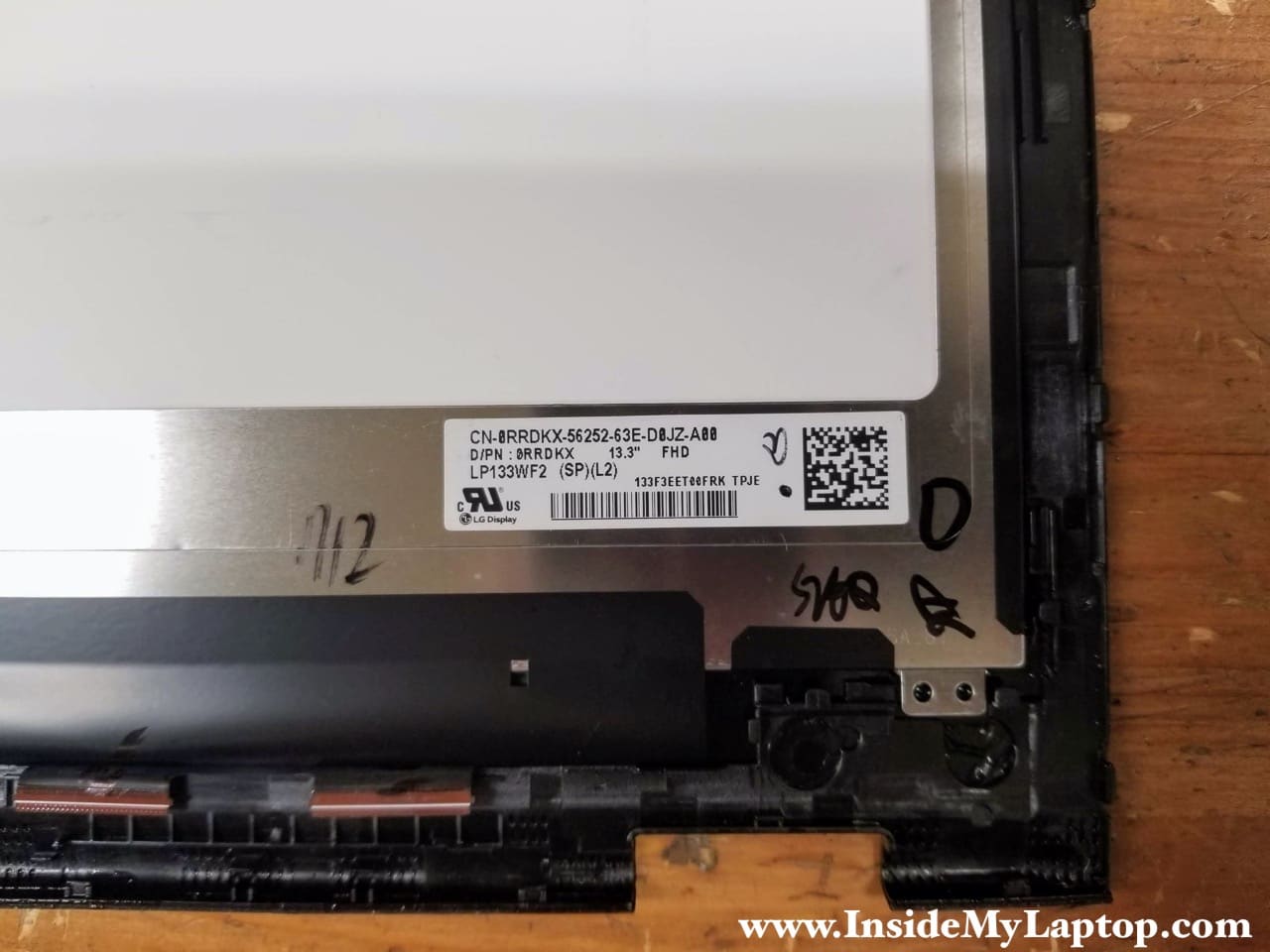
The LCD screen is permanently glued to the front digitizer glass and cannot be removed separately.

You can find a new replacement touchscreen assembly if you search the Dell part number printed on the original part. In my case the part number is 0RRDKX.
I believe you can use the same touchscreen for Dell Inspiron 7347, 7348, 7352, 7352, 7359 laptops but do your research.
Installing the new touchscreen
The cables on both side are very short so you’ll have very limited space to work. I would recommend placing something (like a piece of foam) under the screen to elevate it a little bit. Reconnect all the cables and start snapping the touchscreen back in place on the lower side of the display assembly. Make sure all the cables are routed correctly.
Test the laptop video before you snap the touchscreen back in place completely.