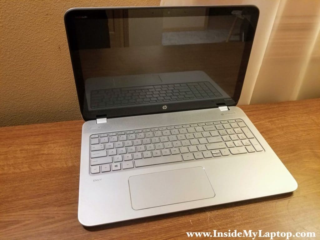
In this guide I show how to disassemble an HP ENVY m6-n101dx laptop. Most likely this guide will work for some other models in the HP ENVY m6-n computer line.
This will be a long disassembly guide. Be organized. Keep track of all removed screws and cables.
At the end of this guide you will find a link to the official HP ENVY m6 manual. In the manual you can find a list of spare parts numbers.
STEP 1.
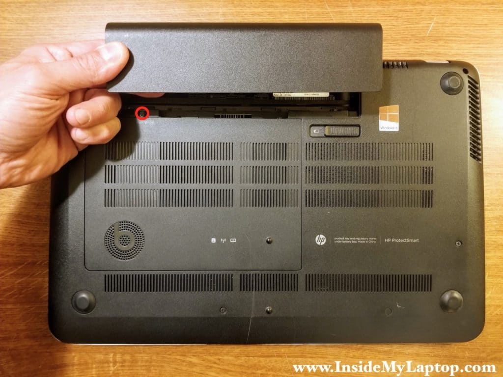
Unlock and remove the battery.
Remove one screw securing the service cover.
STEP 2.
Remove the service cover.

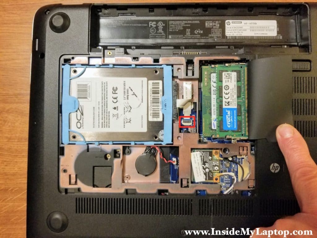
Under the service cover you can access the hard drive, both memory modules, RTC battery and wireless card.
STEP 3.
Disconnect the hard drive cable from the motherboard.
Both RAM slots can be accessed here. This laptop supports up to 16GB (2x8GB) DDR3-12800 SODIMM RAM modules.
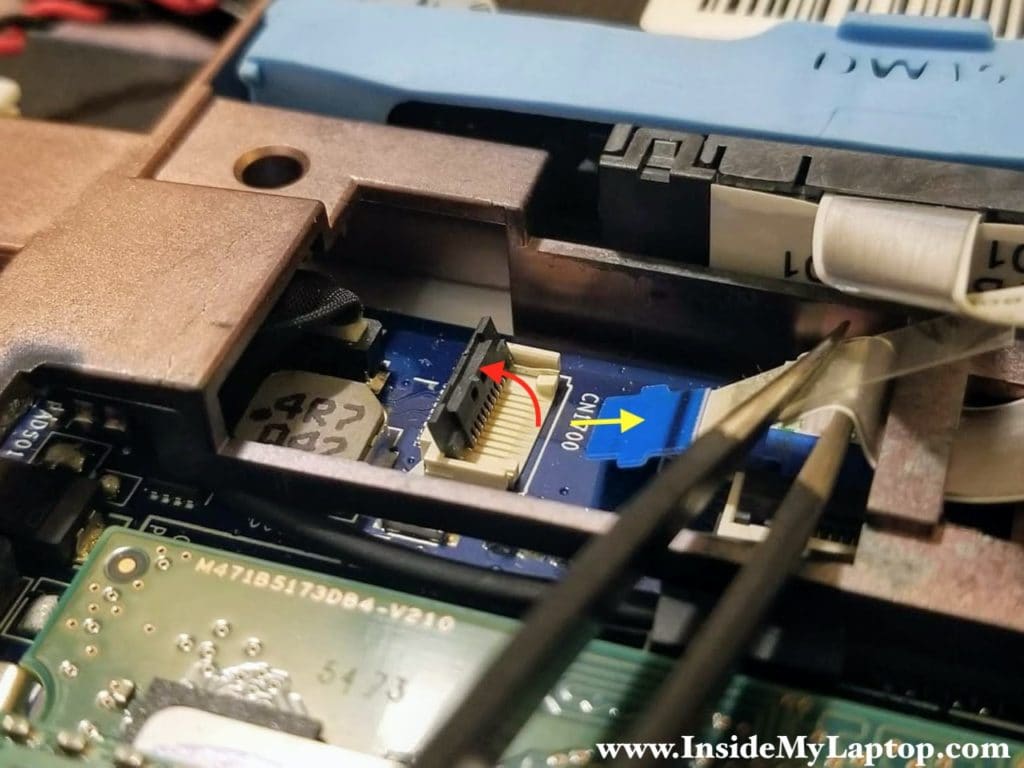
Here’s how to disconnect the hard drive cable.
1. Lift up the locking tab at a 90 degree angle to unlock the connector (red arrow).
2. Lift up and pull the hard drive cable out.
STEP 4.
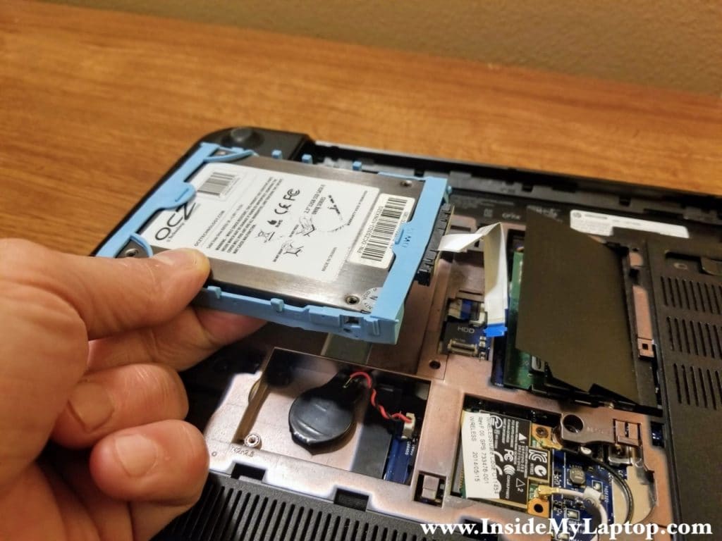
Remove the hard drive.
The rubber bracket and SATA cable have to be transferred to the new drive if you are replacing it.
If you have a regular 2.5″ hard drive installed I would recommend upgrading it to a 2.5″ SSD drive.
STEP 5.
Remove all screws securing the bottom cover.
HP ENVY m6-n101dx uses many different types of screws on the bottom. Keep track of them as I mentioned in this guide for beginners.
Also, unplug the RTC battery cable from the motherboard. It’s necessary for removing the bottom cover.
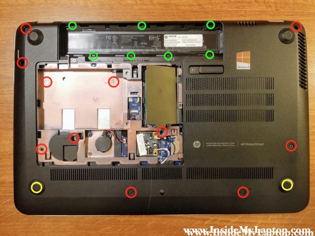
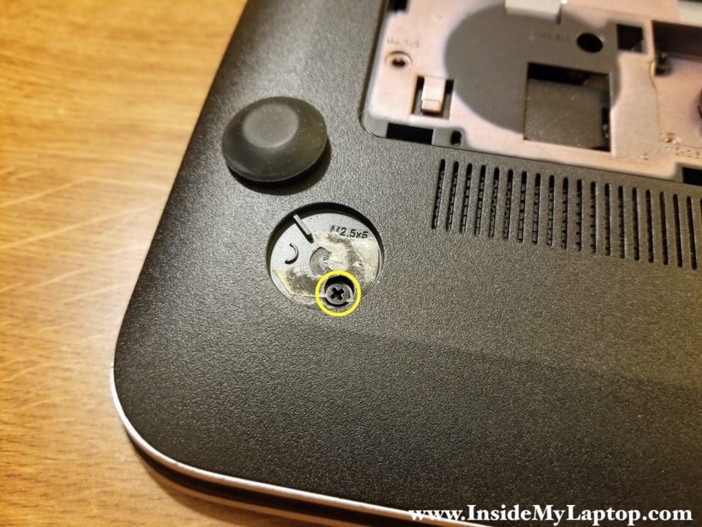
Don’t forget two hidden screws located under the lower left and right feet.
STEP 6.
Start separating the bottom cover from the rest of the laptop.

STEP 7.
Remove the bottom cover.
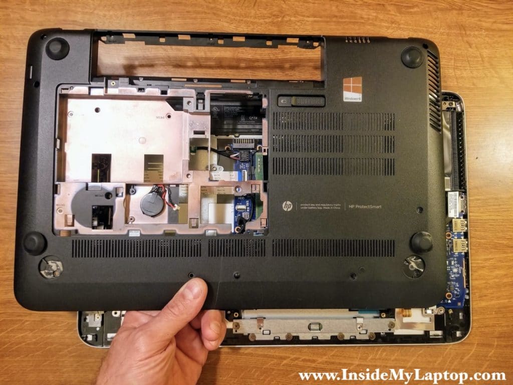
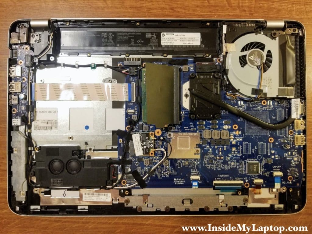
There are many different cables routed on the top case and motherboard.
Take notes ore memorize how they are routed.
STEP 8.
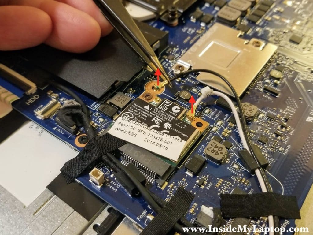
Disconnect both antenna cables from the wireless card.
Lift up the connector to unsnap it from the card.
STEP 9.
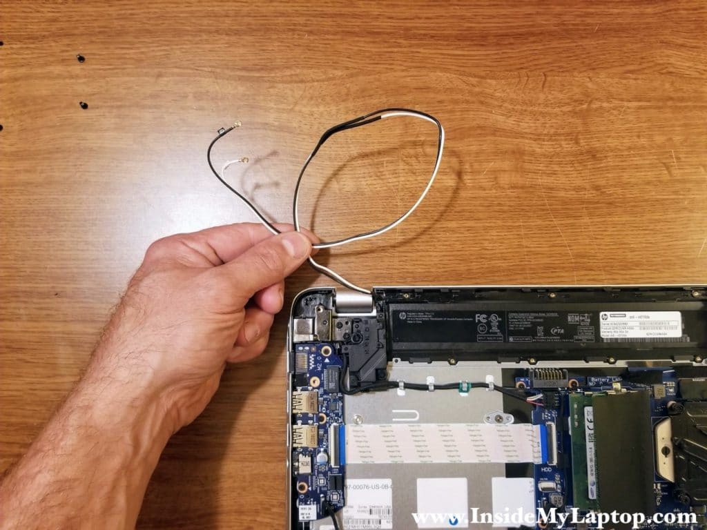
Un-route both wireless antenna cables from the guided path on the motherboard.
STEP 10.
Disconnect the display cable and webcam/microphone cable from the motherboard.
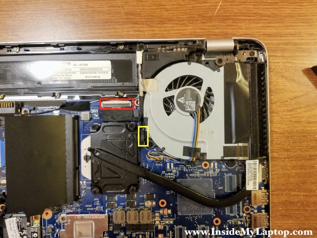
Here’s how to disconnect the display cable.
Unlock the connector (red arrow) and pull the cable out (yellow arrow).

STEP 11.
Un-route both cables from the guided path.
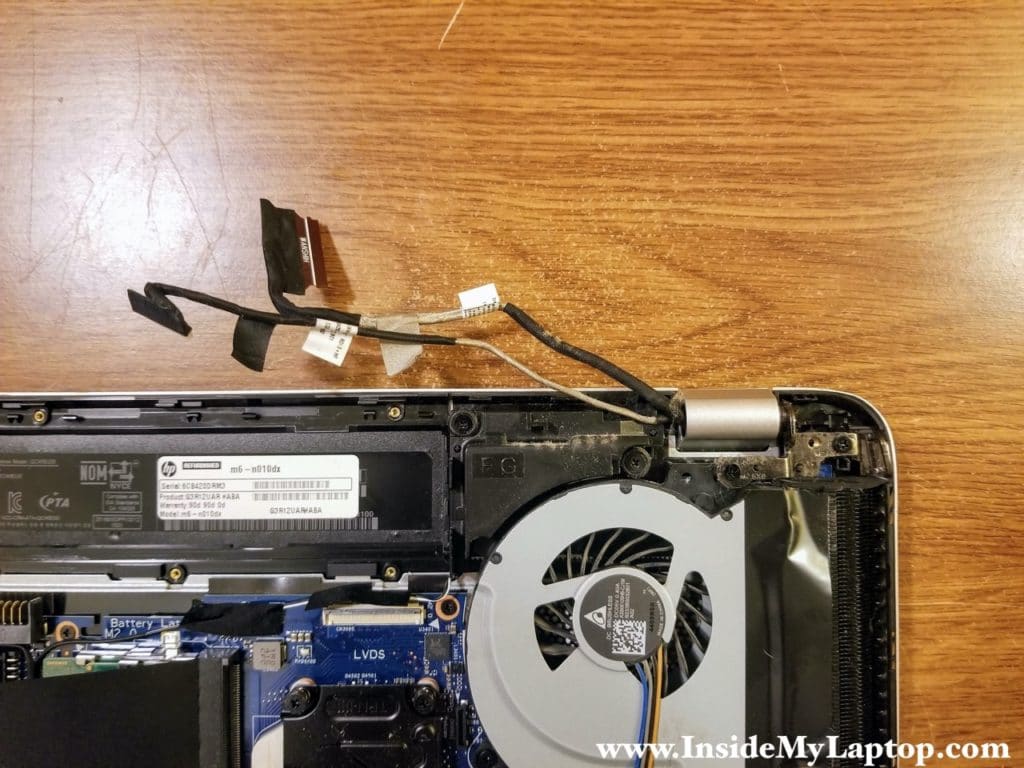
STEP 12.
Remove four screws securing the left and right display hinges.
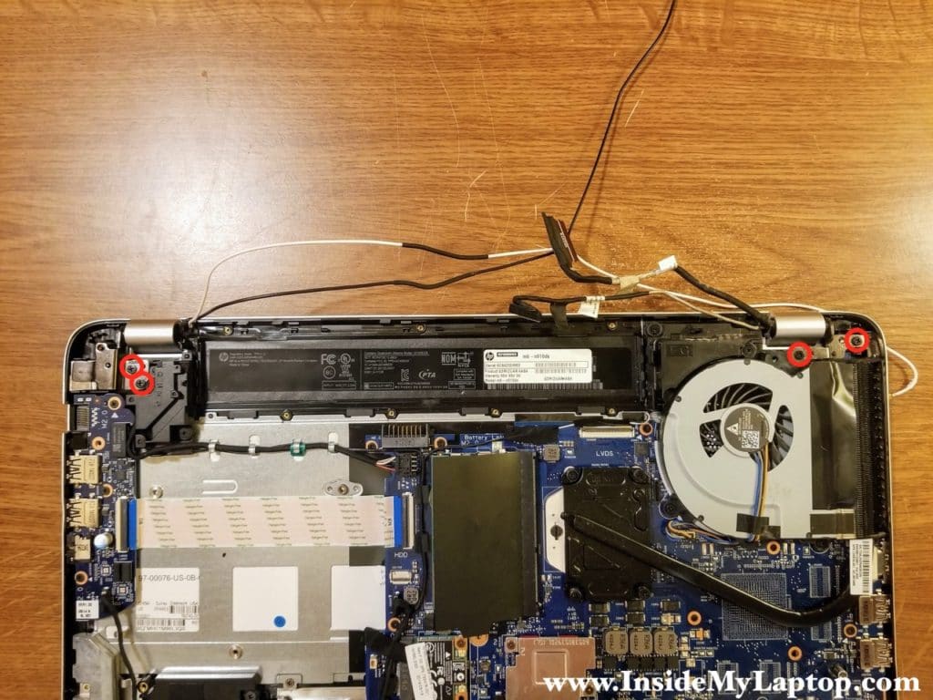
STEP 13.
Lift up both display hinges as it shown on the following picture.
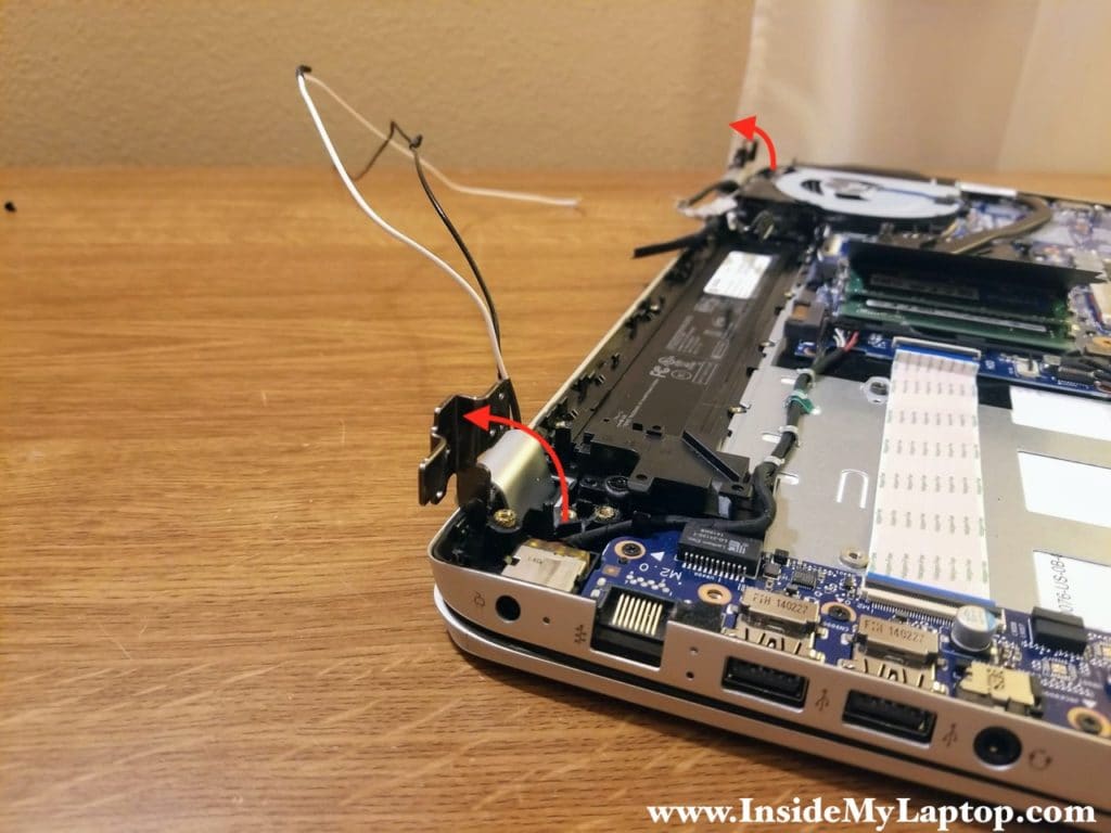
STEP 14.
Separate the top case assembly from the display assembly.
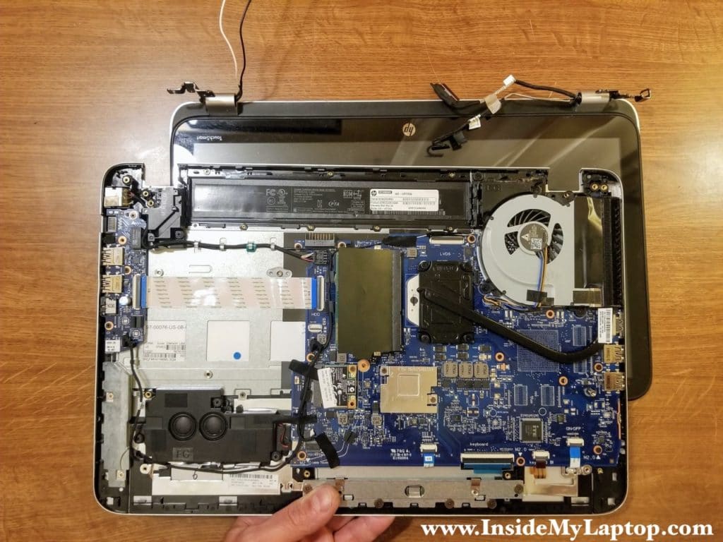
HP ENVY m6-n101dx has terrible hinge area design and it’s highly prone to breaking. Take a closer look at the screw anchors imbedded in thin plastic.
One of the anchors broke off completely (red arrow) and two other got pulled up from the plastic housing (yellow arrows).
How these weak screw anchors are supposed to support a massive display? I don’t know.

STEP 15.
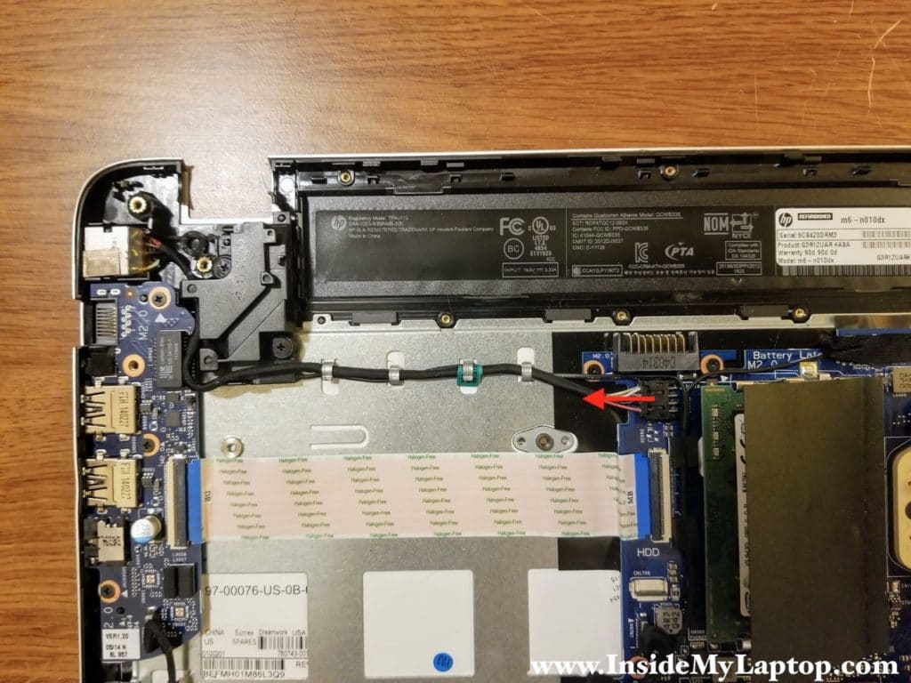
Disconnect the DC jack cable from the motherboard and un-route the cable.
STEP 16.
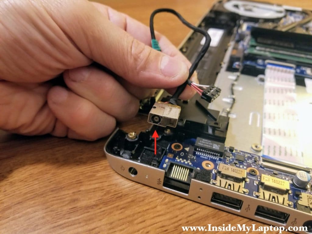
Lift up the DC jack and remove it.
STEP 17.
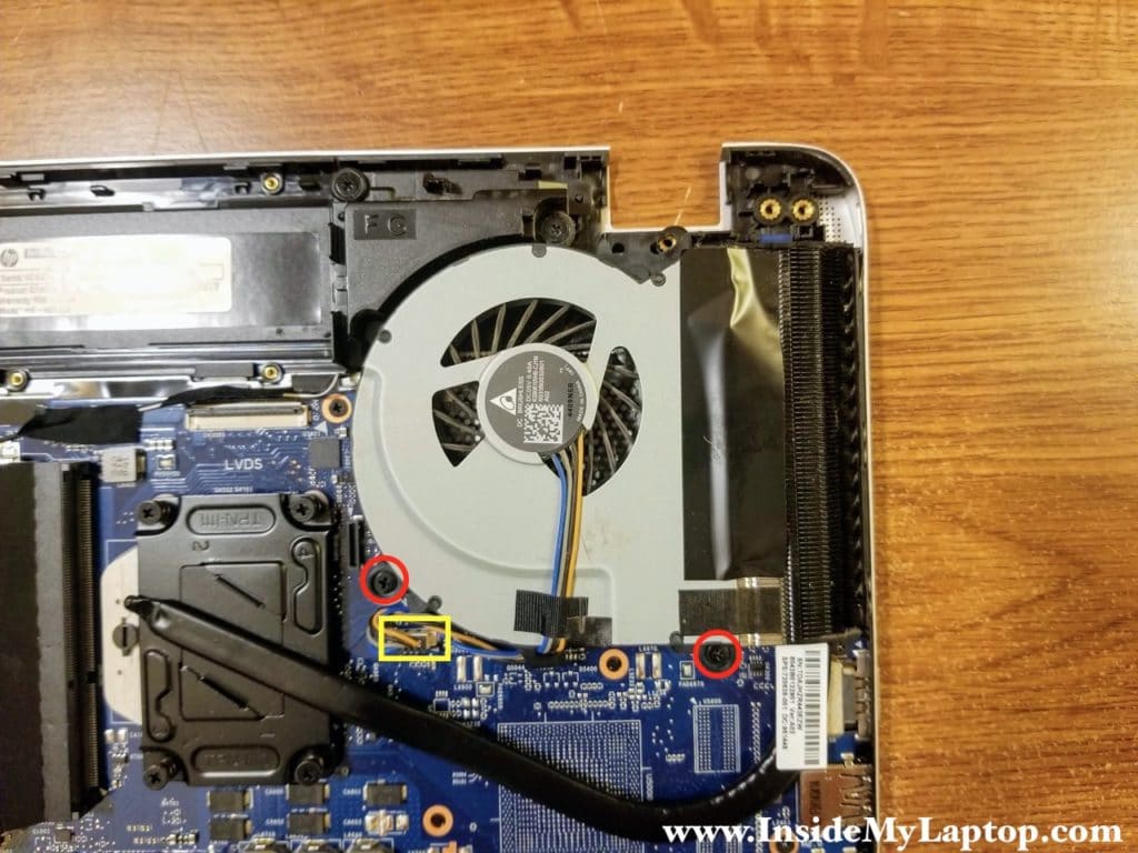
Remove two screws securing the cooling fan. Unplug the fan cable from the motherboard.
STEP 18.
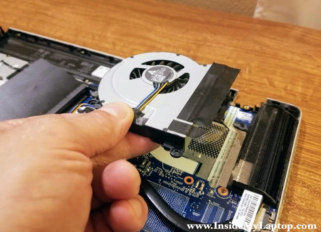
Lift up and remove the fan.
STEP 19.
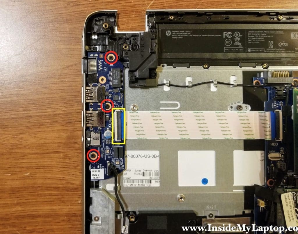
Remove three screws securing the USB/Audio/LAN board and disconnect the I/O cable.
STEP 20.
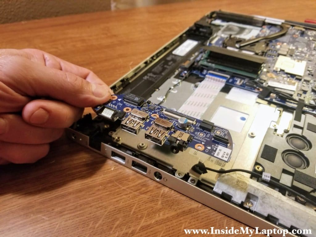
Lift up and remove the USB/Audio/LAN board.
STEP 21.
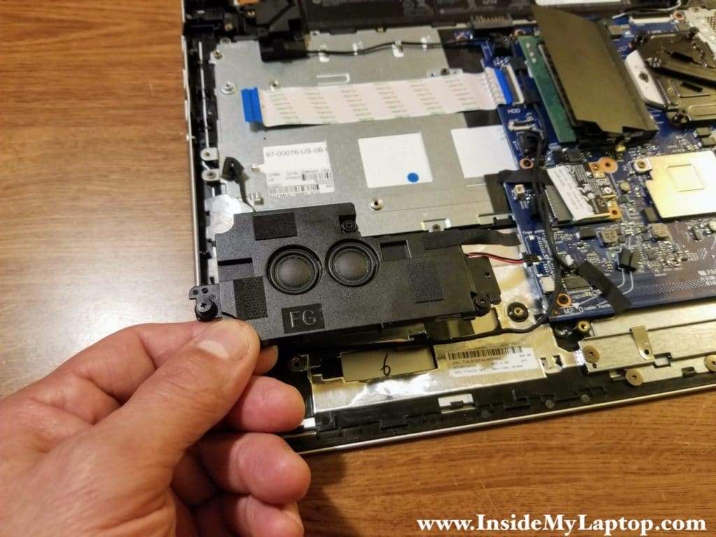
Loosen three screws securing the subwoofer and disconnect the cable.

STEP 22.
Lift up and remove the subwoofer.
STEP 23.
Disconnect the left and right speakers cable.

STEP 24.
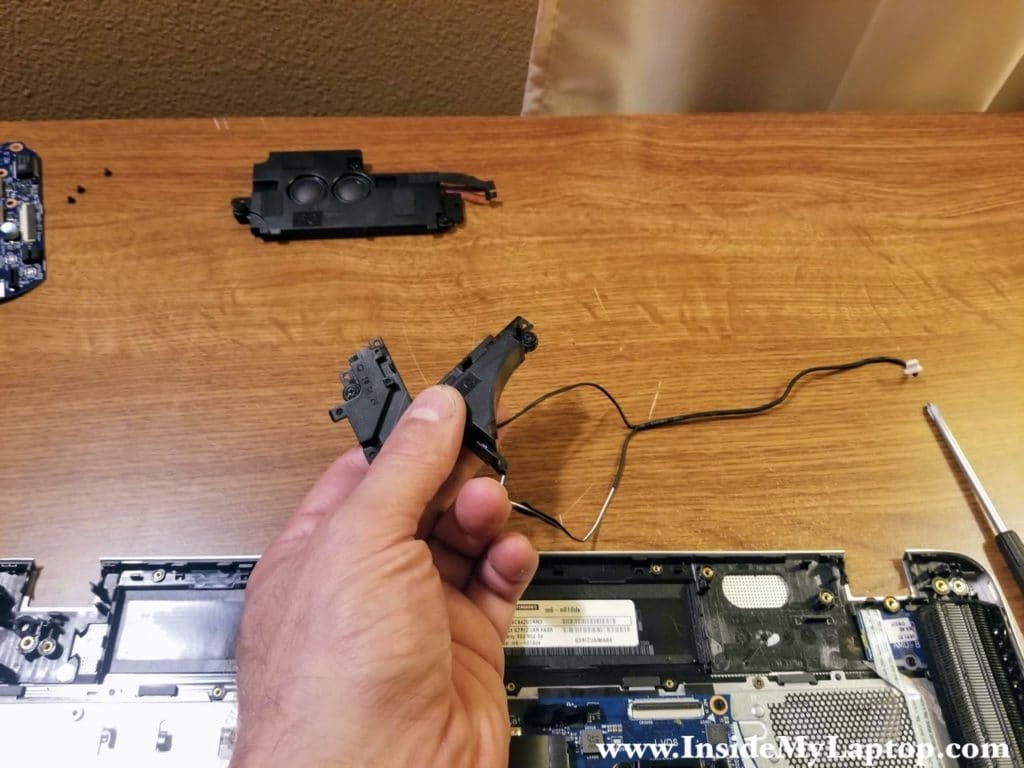
Loosen four screws securing the speakers and un-route the cable from the guided path on the motherboard.

STEP 25.
Remove the speakers.
STEP 26.
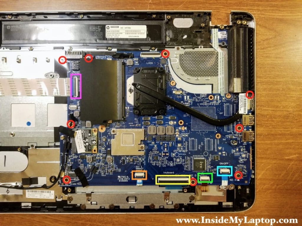
Remove all screws securing the motherboard.
Disconnect the following color-coded cables:
– I/O cable (pink).
– Touchpad cable (orange).
– Keyboard cable (yellow).
– Keyboard backlight cable (green).
– Power button board cable (blue).
STEP 27.
Lift up and remove the motherboard.
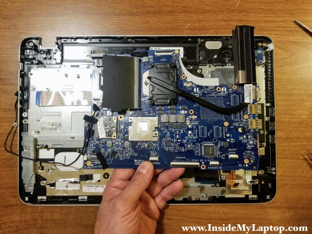
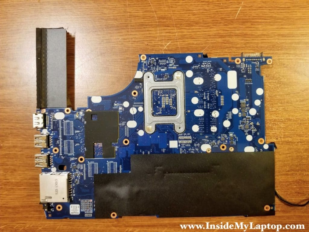
Here’s a photo of the other side.
STEP 28.
Remove one screw securing the power button board.
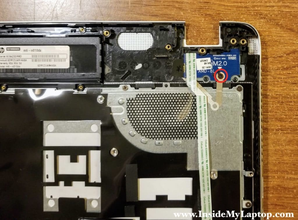
STEP 29.
Separate the cable from the top case (secured with adhesive) and remove the power button board.
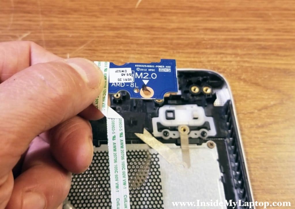
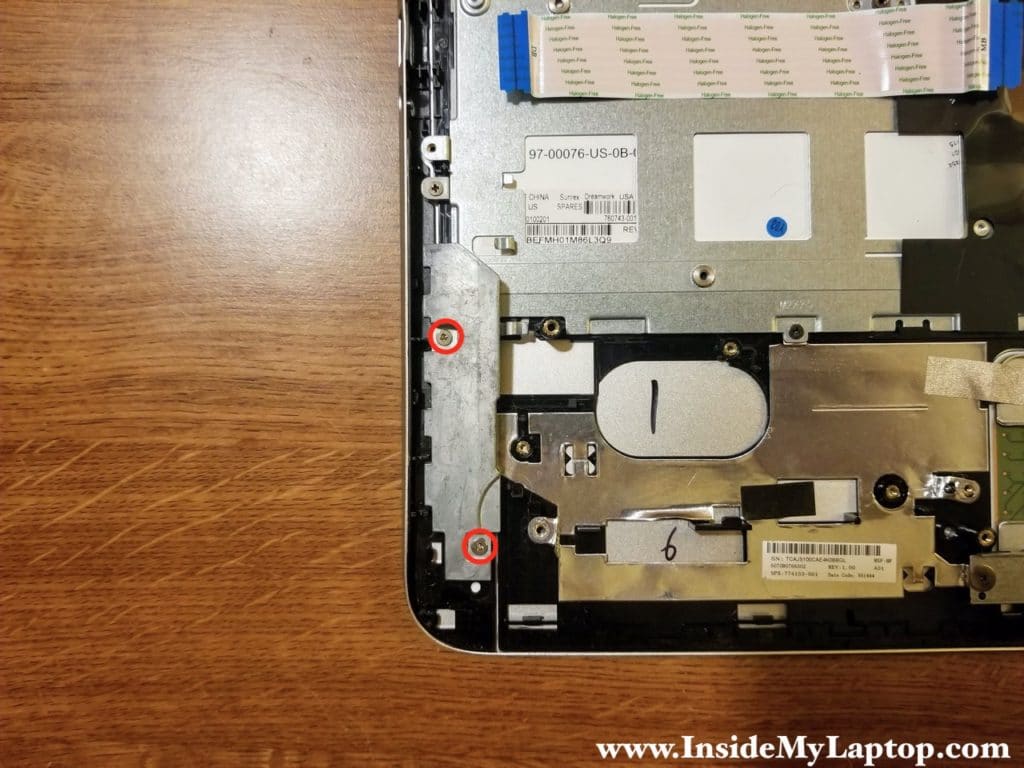
STEP 30.
Remove two screws securing a metal bracket. I assume it is a counterweight for the massive display. Remove the bracket.
STEP 31.
Remove nine screws securing the keyboard cover.
Slide the cover down (yellow arrow) to disengage it from the top case and remove the cover.
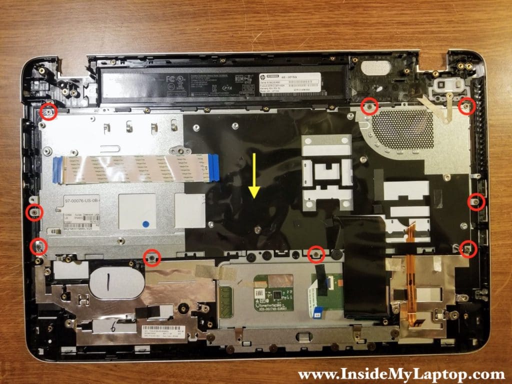
While removing the cover you’ll have to pull the keyboard cable through the opening.

STEP 32.
Slide the keyboard to the shown direction to disengage from the top case.

STEP 32.
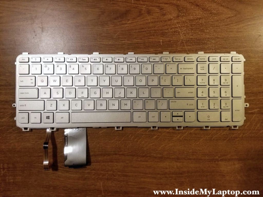
Remove the keyboard.
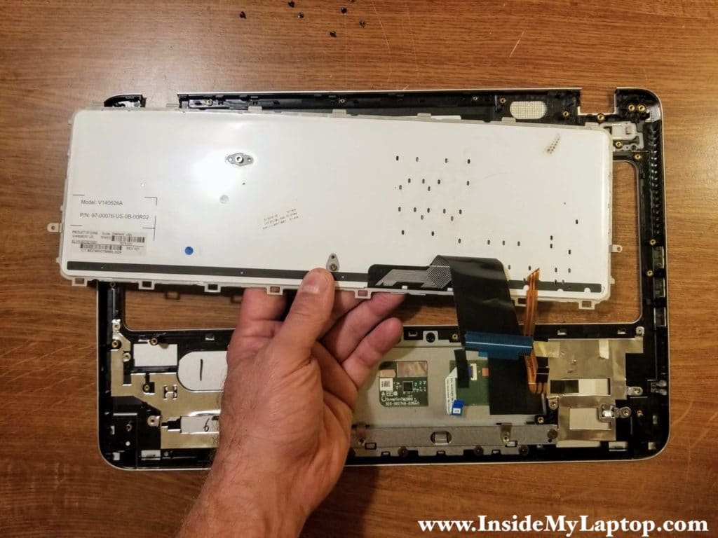
Now you can replace the keyboard if necessary.
HP ENVY m6-n101dx keyboard part number: 760743-001.
The touchpad also can be easily accessed and replaced if necessary.
