In this tutorial I explain how to disassemble Lenovo Yoga 700-11ISK Touch. Laptop model 80KE004YUS.
At the end of this guid I’ll attach a link to the YOGA 700-11ISK hardware maintenance manual.
In the maintenance manual you will find all official disassembly instructions, specs of screws used in the laptop and a full list of spare parts numbers.
STEP 1.
Remove all screws from the bottom cover.

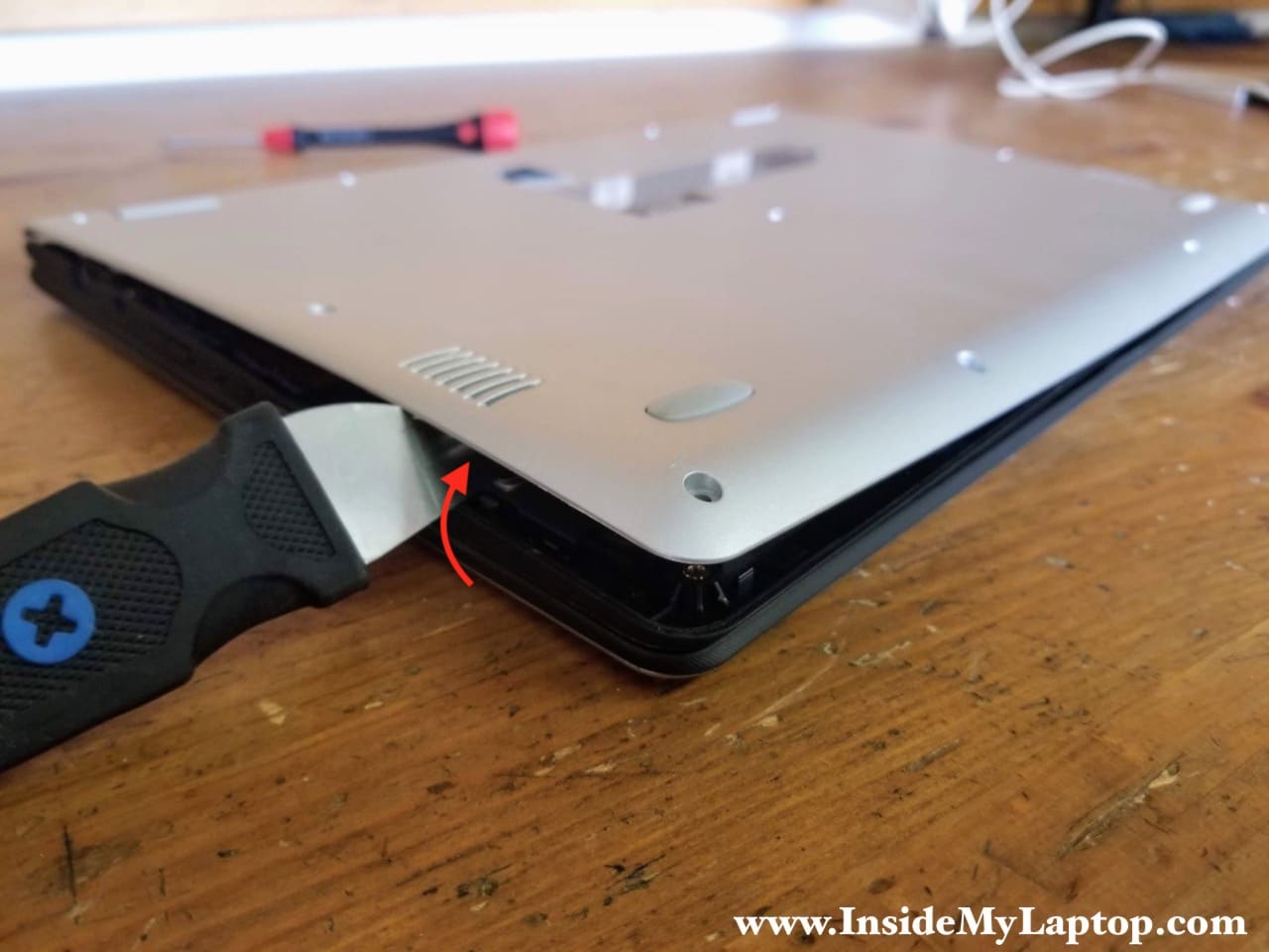
STEP 2.
Carefully separate the bottom cover from the rest of the laptop.
STEP 3.
Remove the bottom cover.

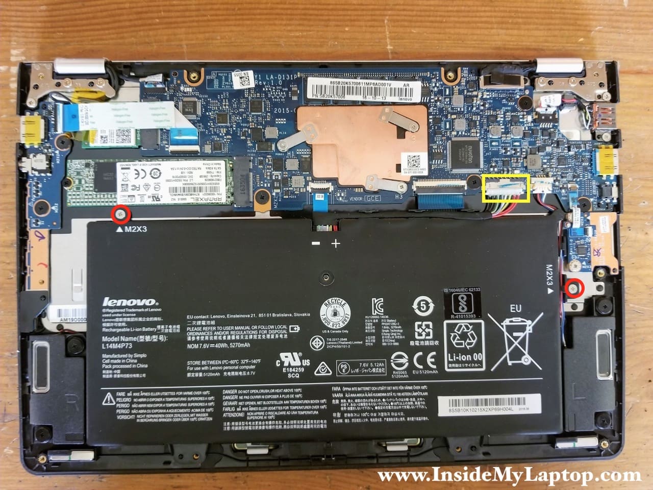
STEP 4.
Remove two screws securing the battery and disconnect the battery cable from the motherboard.
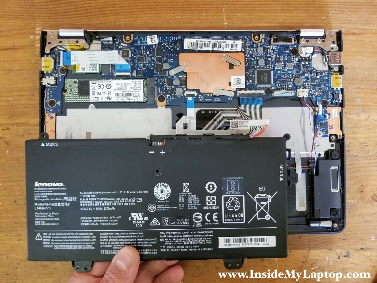
STEP 5.
Lift up and remove the battery. Replacement battery type L14M4P73.
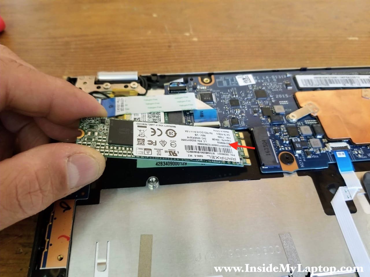
STEP 6.
Remove one screw securing the SSD. Pull the SSD out.
This laptop supports m.2 SATA III solid state drives (type 2280).
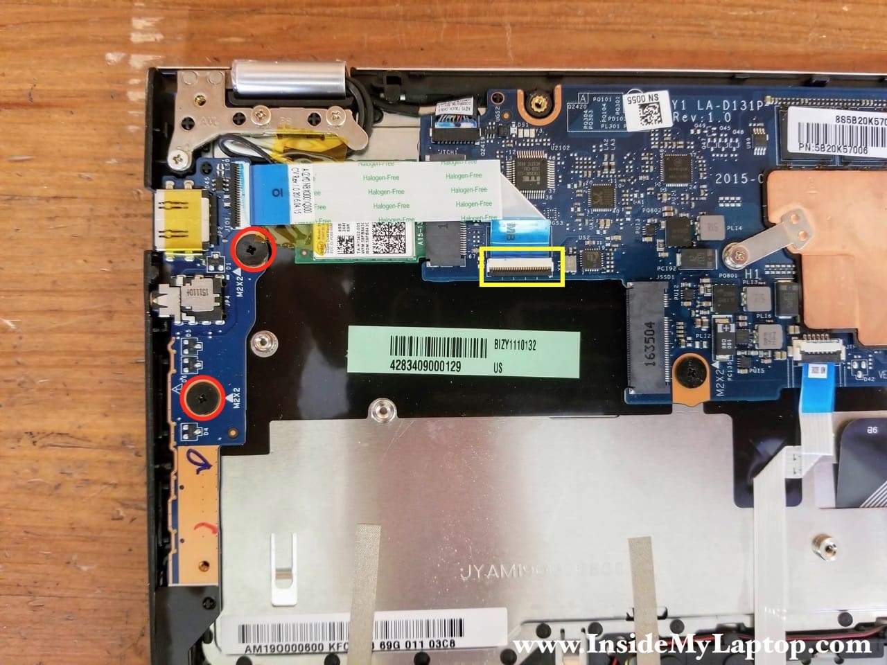
STEP 7.
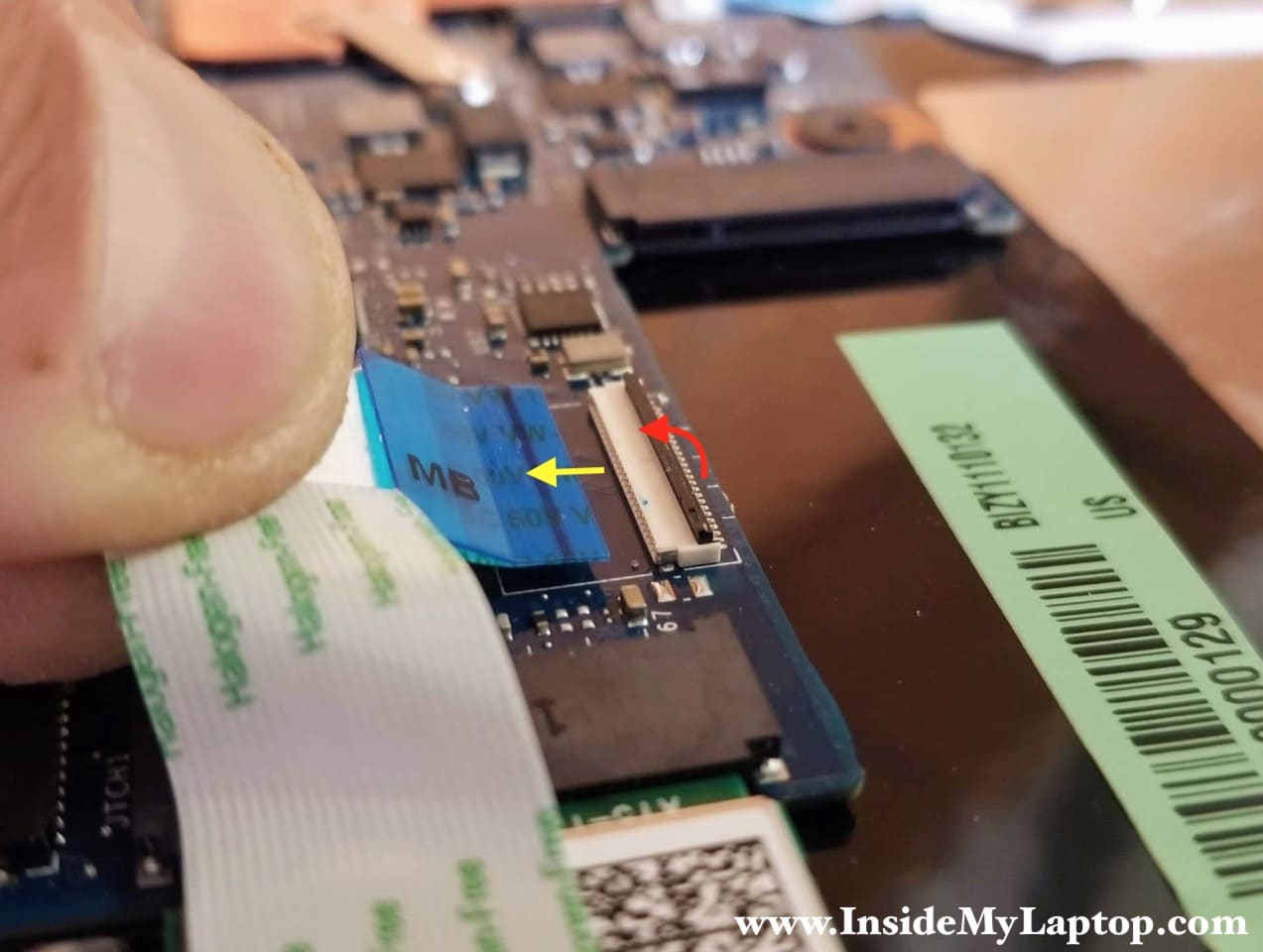
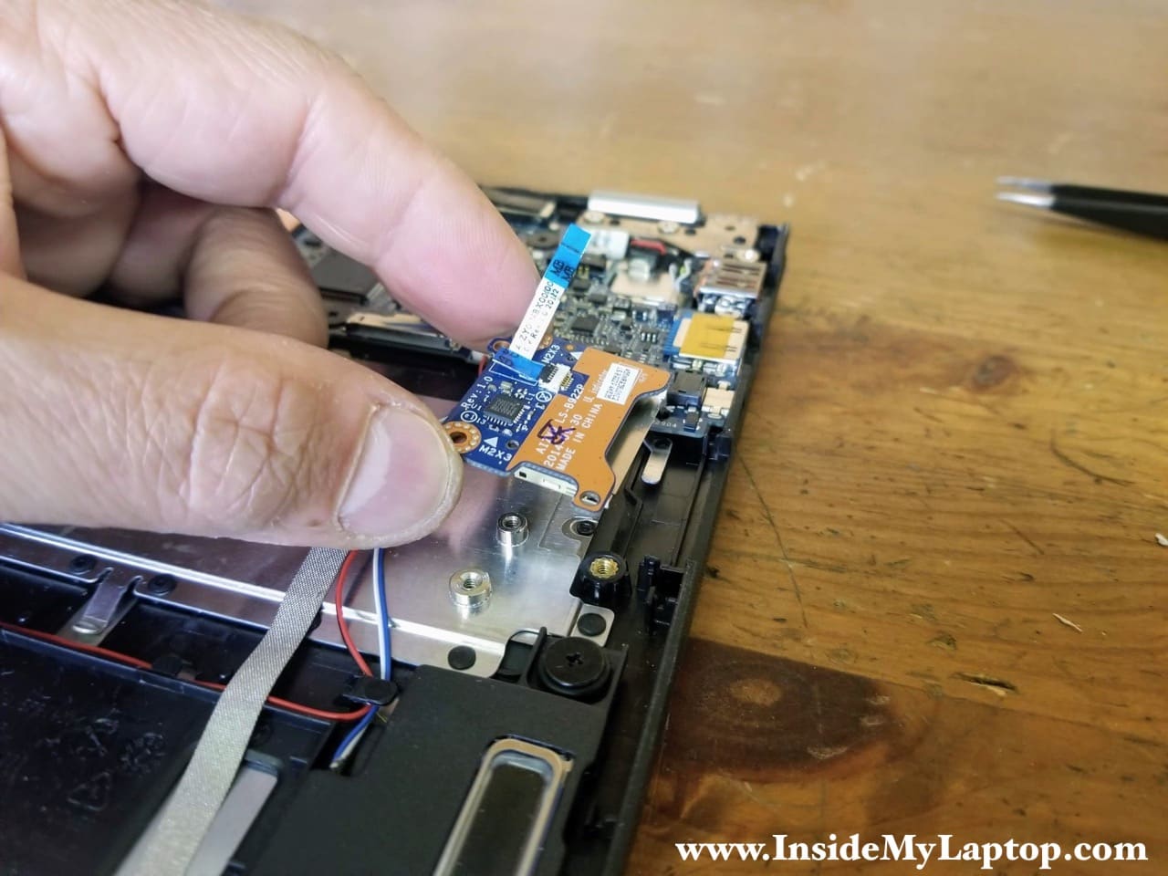
Remove two screws securing the audio USB power button board. Disconnect the flat cable from the motherboard.
Here’s how to disconnect the cable. Unlock the connector first by lifting up the locking tab (red arrow). After that pull the cable out (yellow arrow).
STEP 8.
Remove the audio USB power button board with the cable.

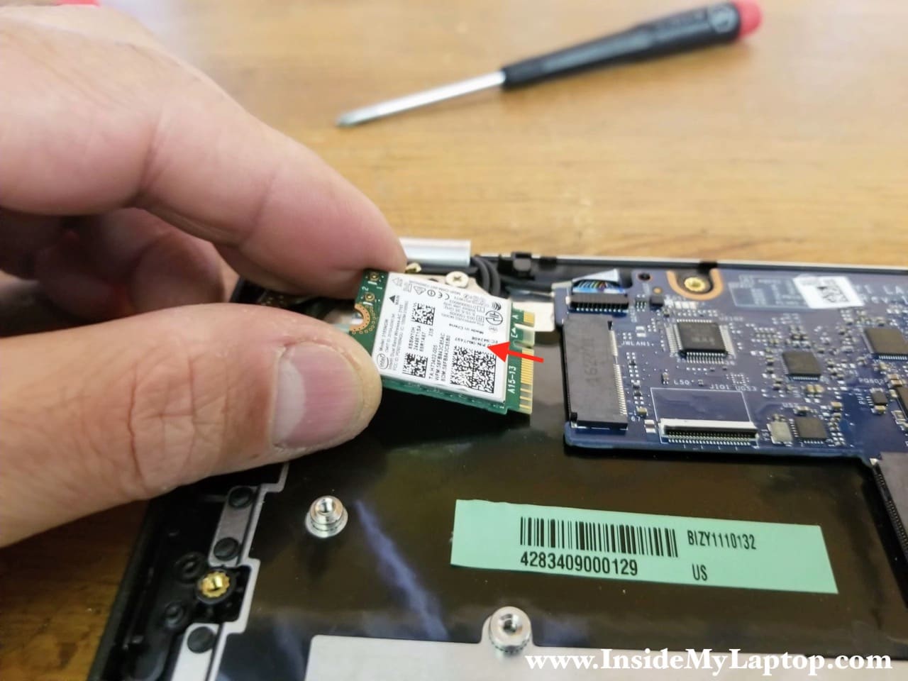
STEP 9.
Disconnect both antenna cables from the wireless card. Remove one screw securing the wireless card.

STEP 10.
Pull the wireless card out.
STEP 11.
Disconnect the SD card reader cable from the motherboard. Remove two screws securing the SD card reader board.

STEP 12.
Remove the SD card reader board.
STEP 13.
Disconnect the webcam cable (color-coded in red) and display video cable (color-coded in orange).

Here’s how to disconnect the display video cable. Simply pull it up by the black belt located on top.

STEP 14.
Open up the display 180 degrees. Place the laptop on your desk as it shown on the following picture.
Remove six screws securing the display hinges.

STEP 15.
Separate the display panel from the laptop base.
You can find instructions for taking apart the display panel in the hardware maintenance manual (link at the end).

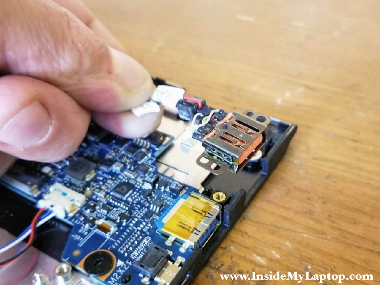
STEP 16.
Remove one screw securing the DC power jack. Disconnect the DC power jack cable from the motherboard.

STEP 17.
Lift up and remove the DC power jack harness.
STEP 18.
Remove four screws securing the motherboard.
Disconnect the following color-coded cables:
– Touchpad cable (orange).
– Keyboard cable (yellow).
– Speaker cable (green).

Here’s how to disconnect flat cables. Unlock the connector and pull the cable out.

STEP 19.
Remove the motherboard.

Here’s a photo of the other side of the motherboard.

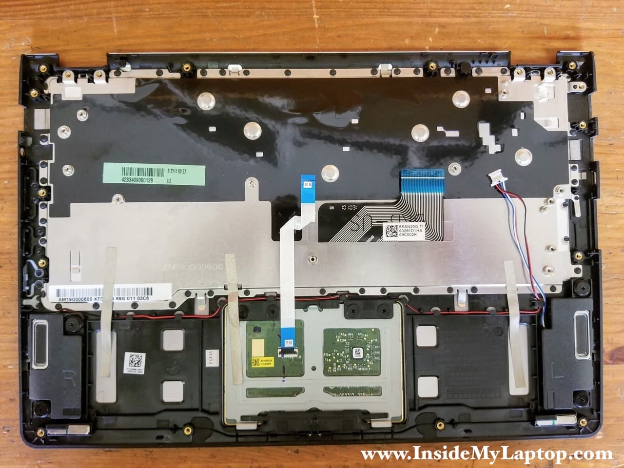
In Lenovo Yoga 700-11ISK Touch laptop the keyboard is permanently attached to the top case and replacing it is not easy. The touchpad and speakers are removable.