
In this guide I explain how to disassemble a Lenovo ThinkPad T570 or ThinkPad P51s laptop. Both models are almost identical. The guide will work for machine types 20JW, 20JX, 20H9, 20HA.
For your convenience, at the end of this guide I will link to the official Lenovo hardware maintenance manual which explains how to properly maintain or troubleshoot the computer in a case of hardware failure.
Some of the Lenovo ThinkPad T570 and P51s laptop design features:
– It’s very easy to remove and replace the keyboard.
– You can have two batteries installed. One mounted outside and another built-in.
– This machines will support either a 2.5″ hard drive or a PCIe NVMe M.2 solid state drive.
– There are two memory slots available for RAM upgrade.
Removing the keyboard
STEP 1.
Unlock and pull out the removable battery. Loosen three captive screws securing the keyboard on the bottom of the laptop.

STEP 2.
Shift the keyboard towards the display. The top side of the keyboard will move under the bezel. It’s possible you will have to apply some reasonable force to make it moving. I had some trouble with that. Eventually I was able to move the keyboard after I used both hands and shifted it in a quick motion.

You know you did it properly when you see a gap between the lower side of the keyboard and the palmrest. Also take a look at the top row of keys, they are almost touching the bezel

STEP 3.
Lift up the lower side of the keyboard and pull it towards the trackpad. Remove the keyboard and turn it upside down on the palmrest.

STEP 4.
Disconnect the keyboard and the trackpoint cables from the motherboard.

Both connectors must be unlocked before removing the cable.
Lift up the locking tab (red arrow) to unlock the connector. After that lift up the cable and pull it out (yellow arrow).

STEP 5.
Now you can remove the keyboard completely.
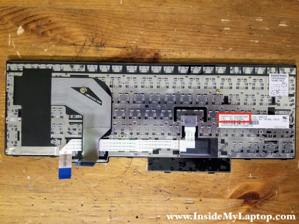
If you need to find a replacement keyboard you can search by the FRU part number printed on the original part.
Lenovo ThinkPad T570 and P51s keyboard part number (US model) is 01EN928.
Removing the built-in battery
The built-in battery is removable but it’s mounted inside the case. It’s necessary to remove to bottom cover in order to access the battery.
STEP 6.
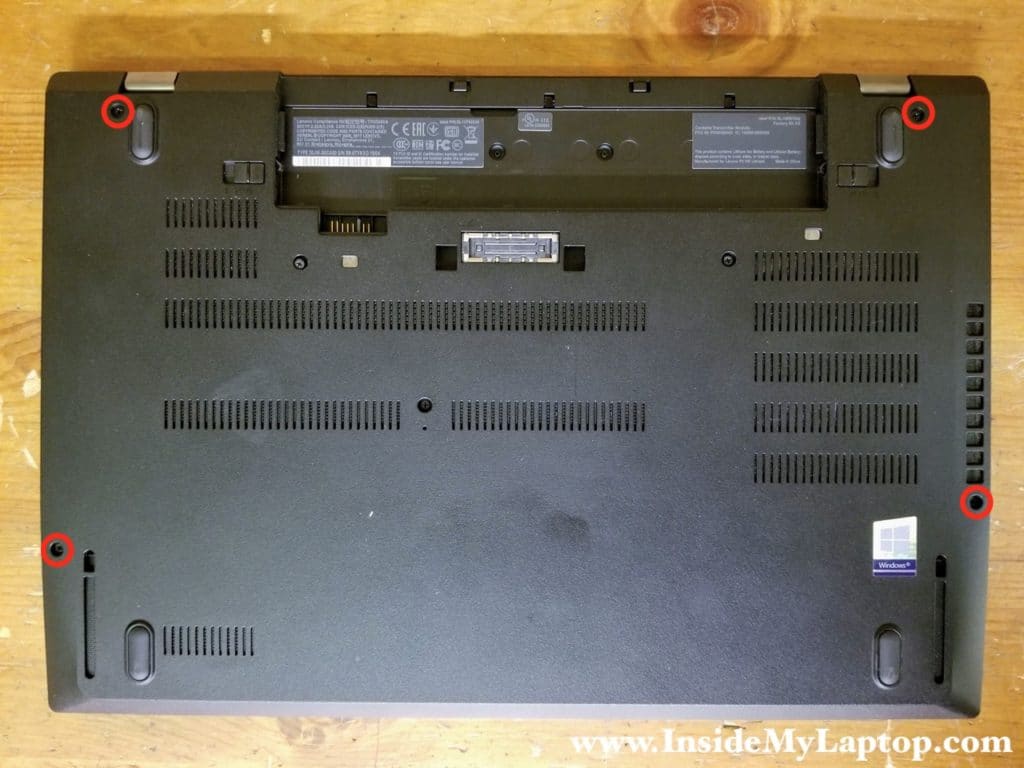
Loosen for captive screws securing the base cover.
STEP 7.
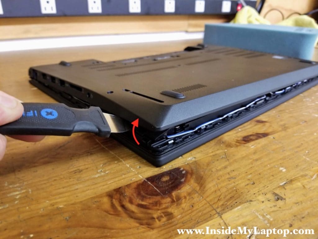
Pry up the base cover using a case opener tool. Continue removing the base cover with your hands.
STEP 8.
Remove the base cover.

STEP 9.
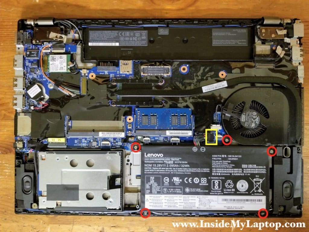
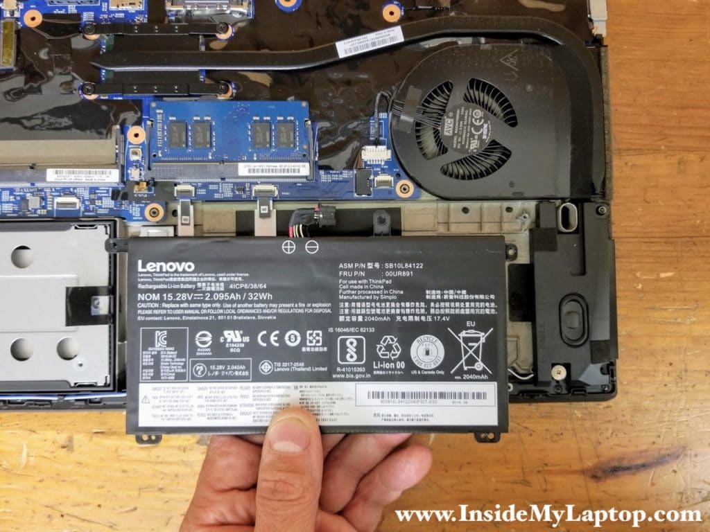
Remove five screws from the battery and disconnect the battery cable from the motherboard.
STEP 10.
Remove the battery.
Lenovo ThinkPad T570 and P51s built-in battery FRU part number: 00UR891.
Removing the hard drive, memory and Wi-Fi card
STEP 11.
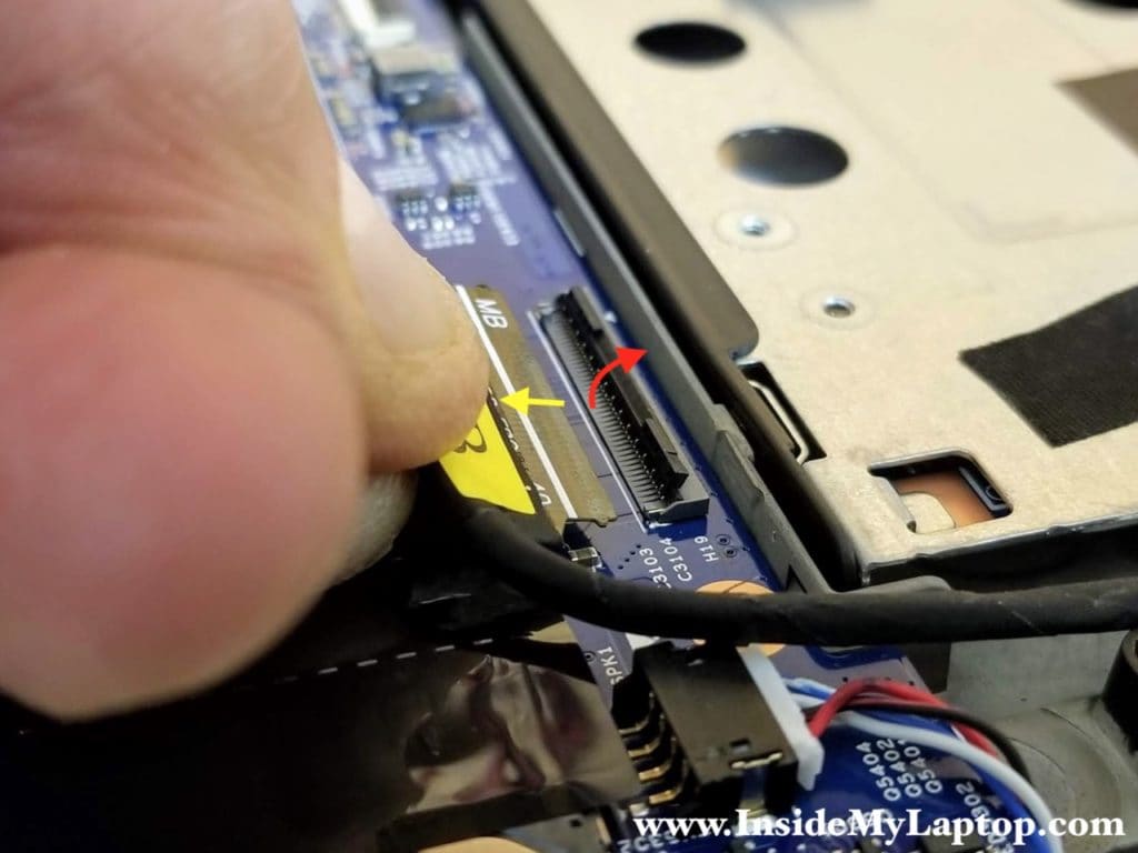
Disconnect the hard drive cable from the motherboard.
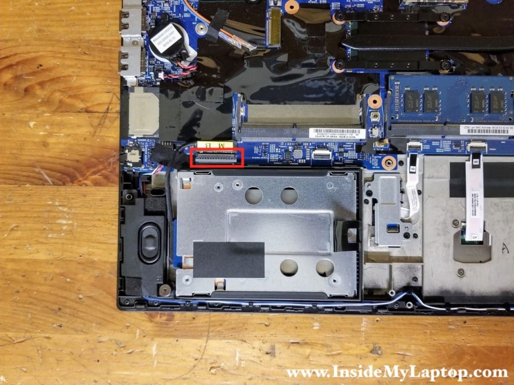
The hard drive cable connector must be unlocked before removing the cable.
STEP 12.
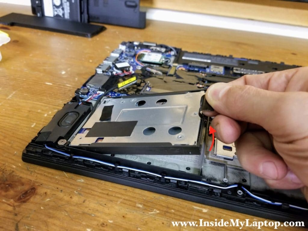
Lift up the right side of the 2.5″ hard drive bracket. There is a small latch securing the bracket on the right side. Pull the black tab to the left to unlock the latch and remove the bracket.
This laptop supports two hard drive interfaces – SATA and M.2 PCIe.
STEP 13.
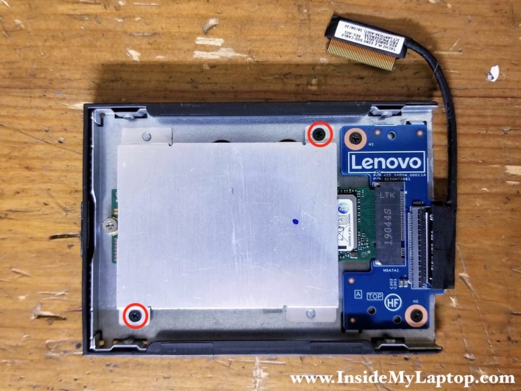
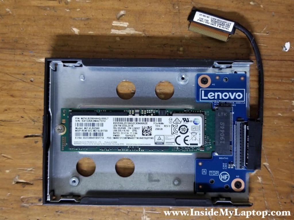
In my laptop I had a 256GB PCIe NVMe M.2 drive installed. It’s connected to the motherboard through a M.2 SSD adapter.
Remove two screws from the SSD heatsink and remove it.
If you have a regular 2.5″ hard drive installed and would like to upgrade it to a PCIe NVMe M.2 solid state drive, you will need to buy a M.2 SSD bracket with adapter (FRU part number 01AY476) and an SSD cable (FRU part number 01ER035).
STEP 14.
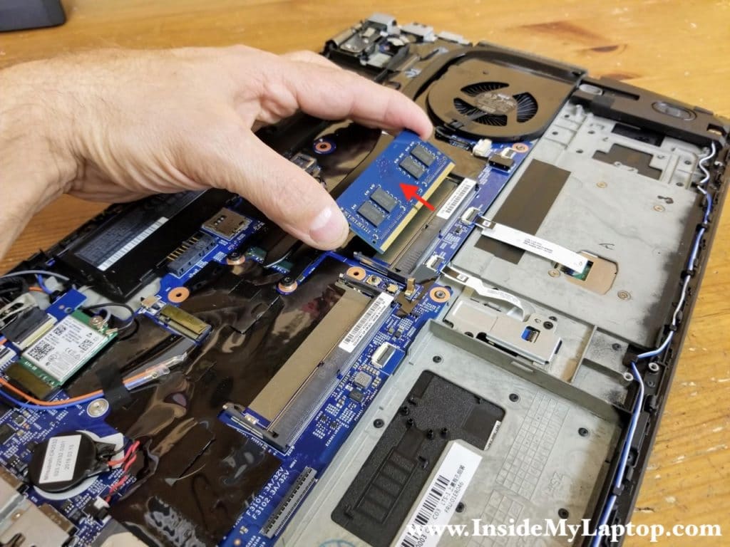
Remove the memory module. This particular laptop came with only one RAM module installed but the motherboard has two slots. You can easily upgrade the memory. ThinkPad T570 and P51s supports up to 32GB RAM DDR4-2666 SODIMM (2x16GB) RAM.
STEP 15.
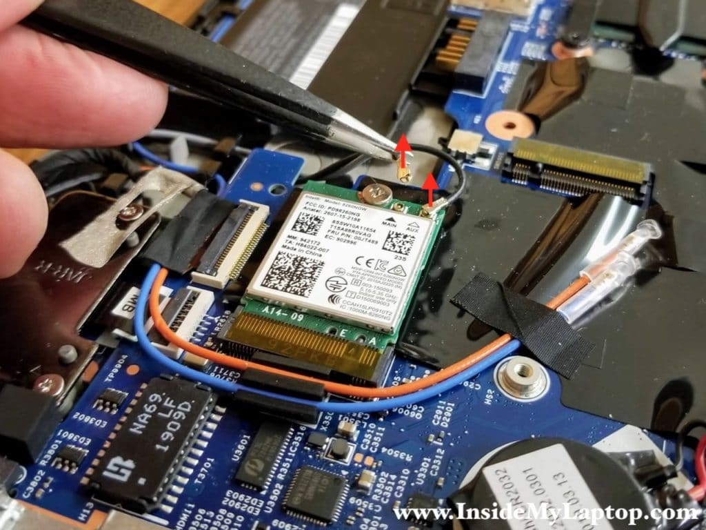
Disconnect two antenna cables from the wireless card.
STEP 16.
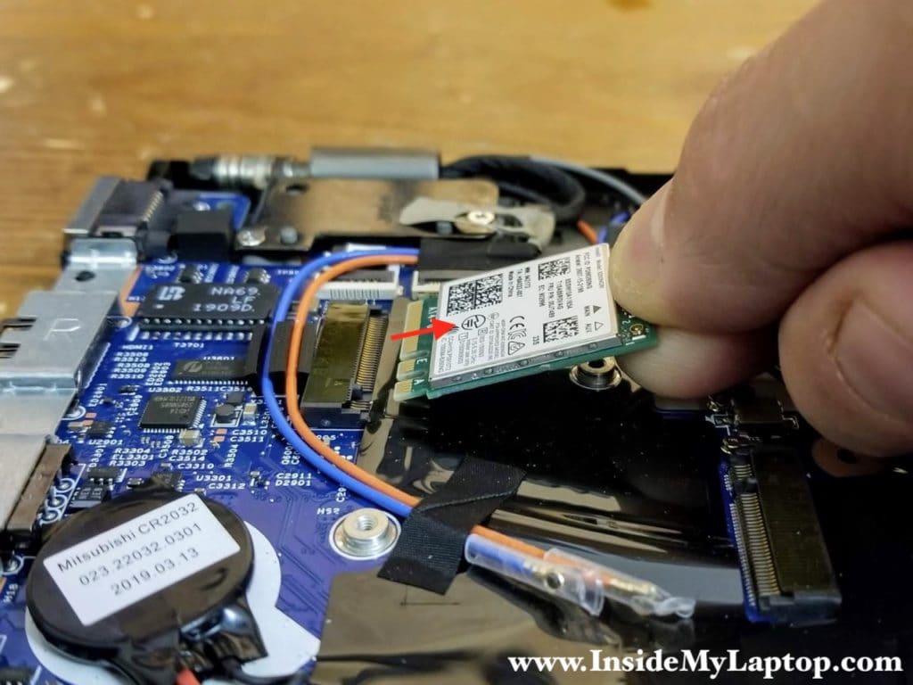
Remove the wireless card.
Removing the display panel
In the next few steps I show how to remove the display panel. It is not necessary to remove the display in order to remove the motherboard, it’s just they way I’m doing it.
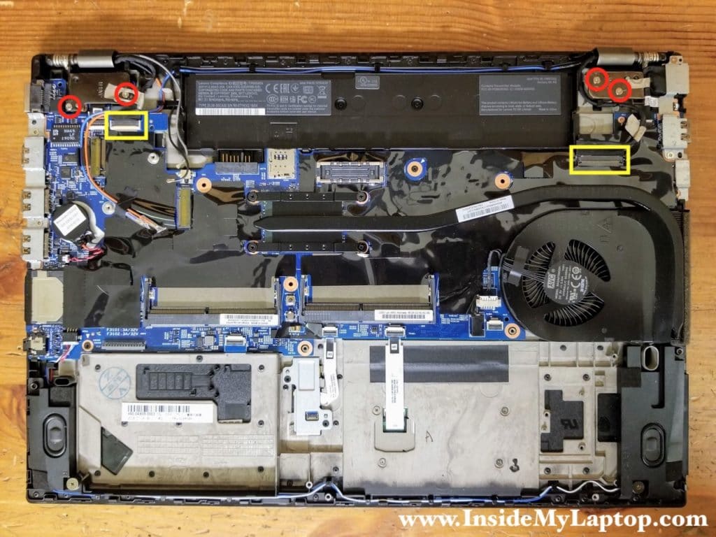
Here’s a closer look at how the cables are routed on the left side. You might need it during the laptop re-assembly.
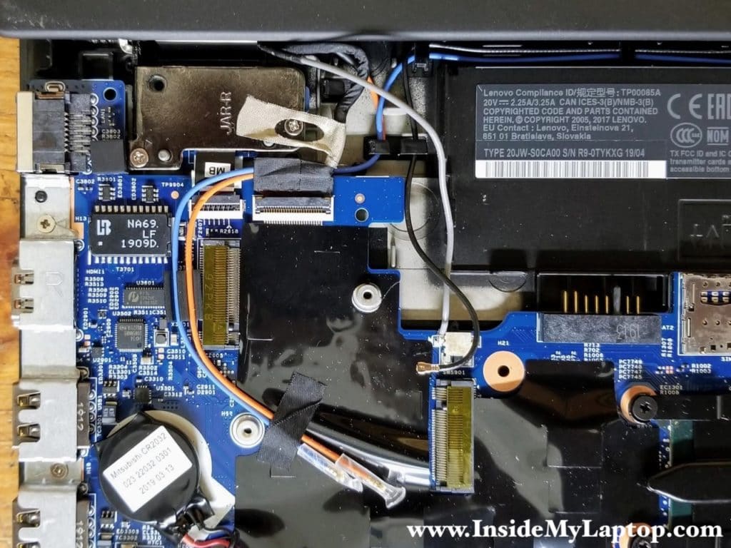
Here’s how to display cable is routed on the right side.

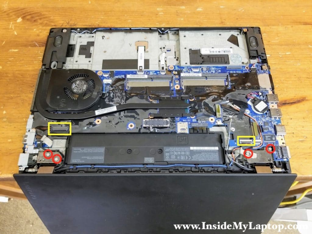
It’s easier to remove the display if you place the laptop as shown on the following picture. Open the display 90 degrees and place the laptop upside down on the edge of the desk.
STEP 17.
Remove four screws from the display hinges and disconnect two display cables from the motherboard. Un-route all display and antenna cables from the guided path on the top case assembly.
STEP 18.
Separate the display panel from the top case assembly.
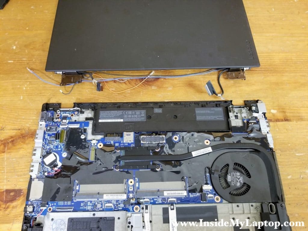
Removing the motherboard
STEP 19.
Remove two screws attaching the power button board to the case and disconnect the cable.

STEP 20.
Remove the power button board.

STEP 21.
Remove two screws securing the DC-IN bracket. Lift up and remove the bracket.
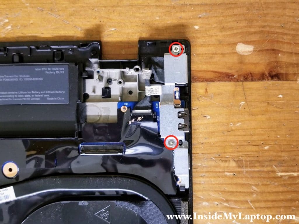
STEP 22.
Disconnect the DC power jack cable from the motherboard and remove the DC jack.
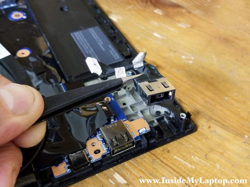
STEP 23.
Remove two screws from the USB bracket and remove the bracket.

STEP 24.
Remove two screw securing the motherboard.
Disconnect the following color-coded cables:
– Speaker cable (orange).
– Fingerprint scanner cable (green).
– Trackpad cable (pink).
I will leave the CMOS battery connected to the motherboard to preserve the BIOS settings.

I will leave the cooling module (heatsink and fan) connected to the motherboard but it can be easily removed. Simply loosen four captive screws and disconnect the cable. After that the cooling module can be separated from the processor. The heatsink assembly FRU part number: 01AY473.

STEP 25.
Carefully separate the motherboard from the top case and remove it. As you see, I left the heatsink assembly connected.
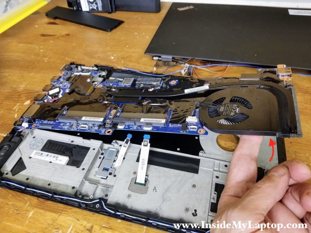
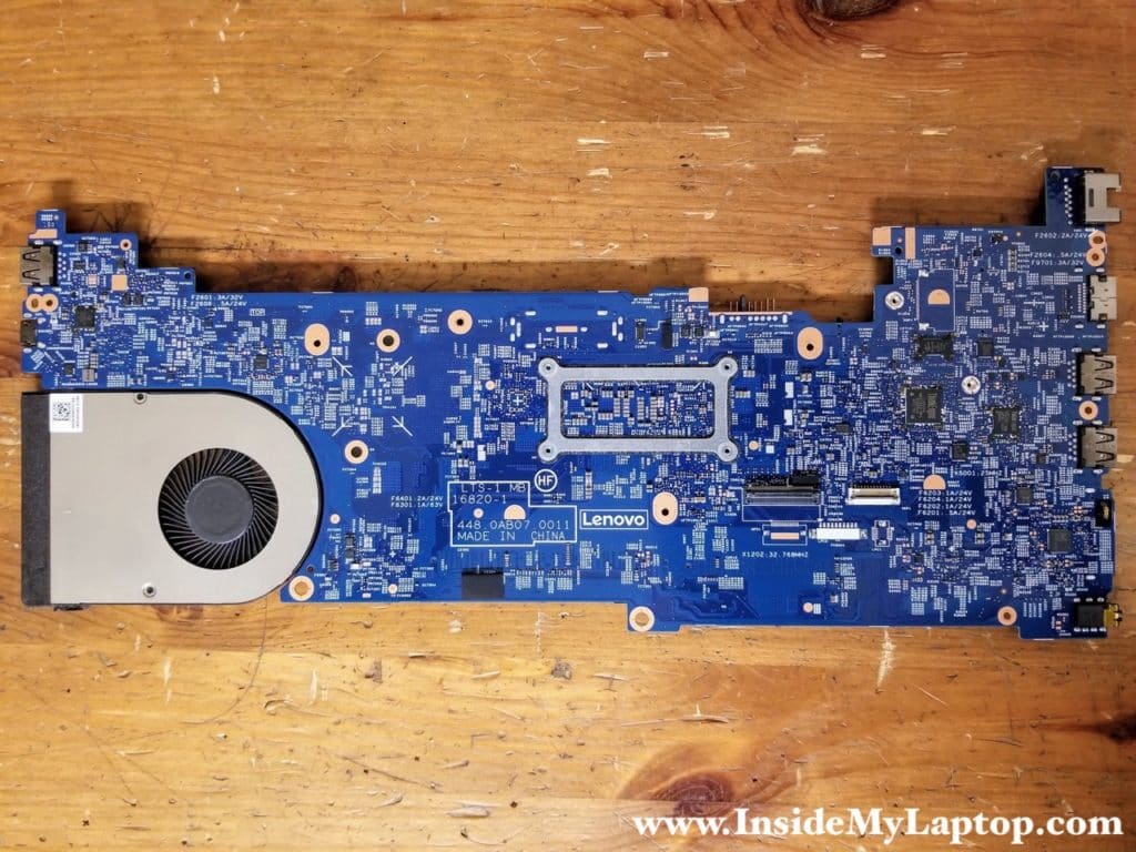
Here’s the other side of the motherboard.
Here’s the top case with the motherboard removed. The fingerprint scanner and trackpad can be easily accessed and replaced if necessary.
