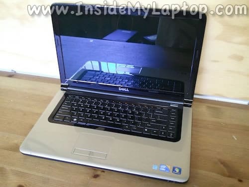
In this guide I will show how to disassemble a Dell Studio 1569.
Before you start, make sure the laptop is turned off.
STEP 1.
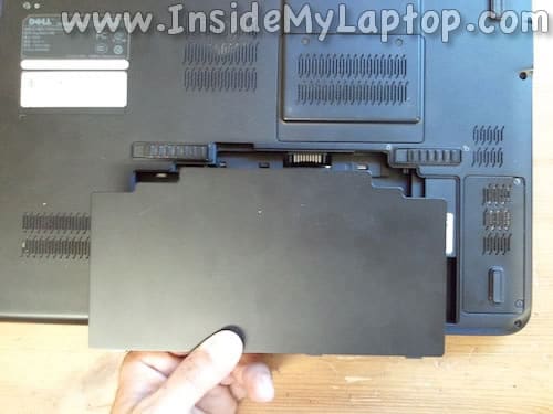
Unlock and remove the battery.
STEP 2.
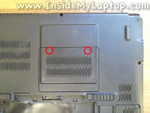
Loosen two screws securing the RAM cover.
Lift up and remove the cover.
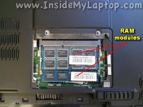
Under the cover you will find both RAM modules.
Dell Studio 1569 uses DDR3 1066/1333 MHz modules and can take up to 8GB RAM total (up to 4GB module in each slot).
You can install up to 8GB (2x4GB) DDR3-12800 SODIMM RAM modules.
STEP 3.
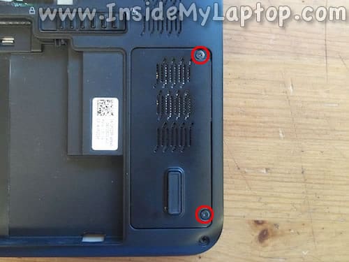
Loosen two screws securing the wireless card cover.
Lift up and remove the cover.
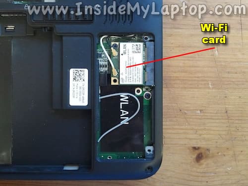
If you need to remove the Wi-Fi card you’ll have to disconnect two antenna cables and remove one screw securing the card.
STEP 4.
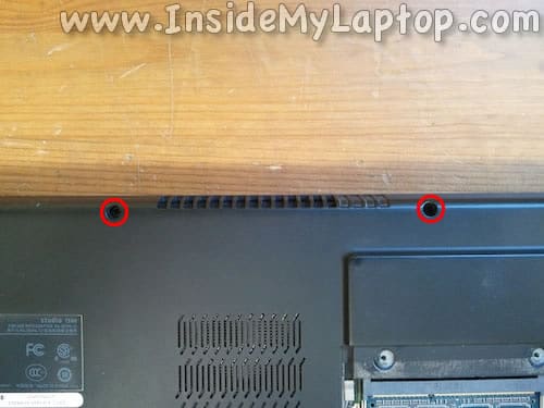
Remove two screws securing the power button cover.
STEP 5.
Start removing the cover as it shown on the following picture.
You’ll have to wiggle the cover on sides to disengage hidden tabs.
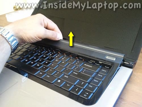
Be careful, the power button cable (attached to the cover) still connected to the motherboard.
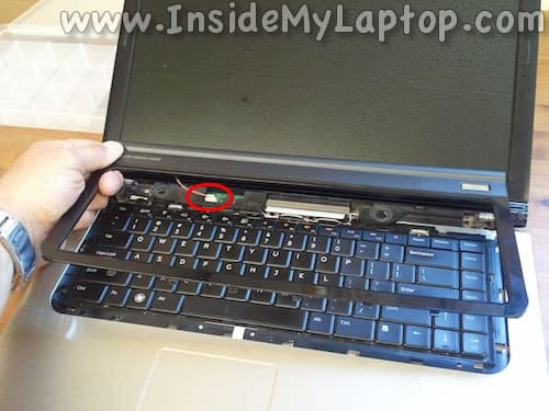
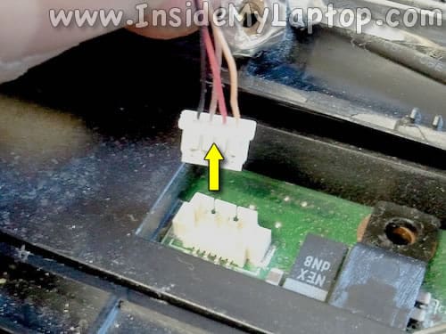
Unplug the power button cable from the connector.
Now you can remove the cover completely.
STEP 6.
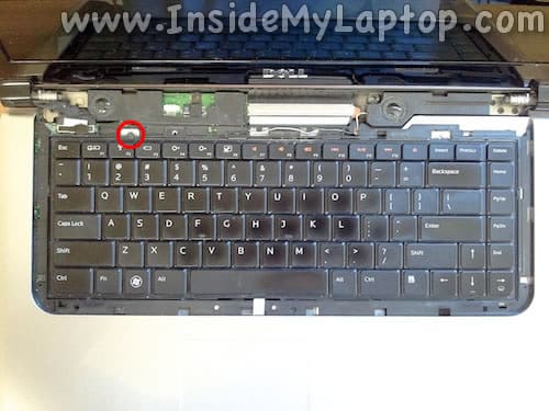
Remove one screw securing the keyboard.
STEP 7.
Separate the keyboard from the palm rest assembly.
1. Slide the keyboard towards the display.
2. Lift up the keyboard.
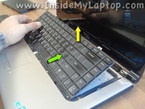
There are two cables connecting the keyboard to the motherboard.
Yellow arrow – backlight cable.
Green arrow – data cable.
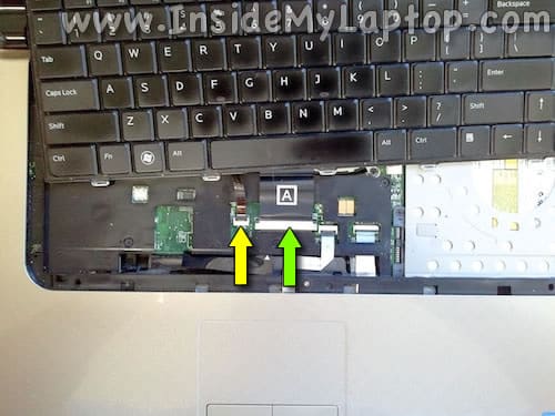
STEP 8.
Here’s how to disconnect the backlight cable.
Lift up the left side of the locking tab until it opens up at a 90 degree angle (green arrow).
Pull the cable from the connector (yellow arrow).
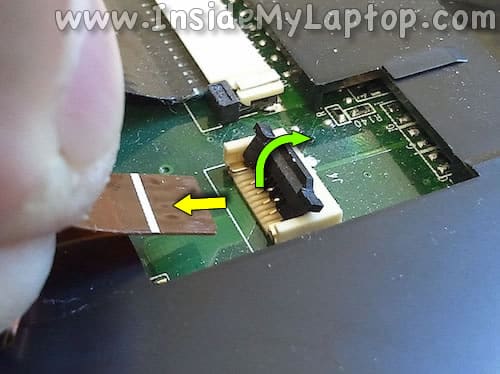
STEP 9.
Here’s how to disconnect the data cable.
Slide the retainer about 2 millimeters away from the connector base (two green arrows).
Pull the cable out (yellow arrow).
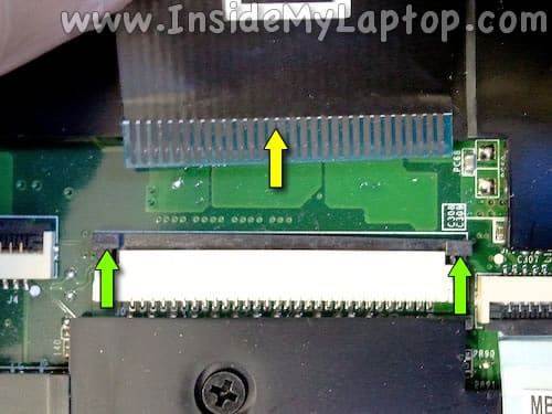
STEP 10.
Remove the keyboard.
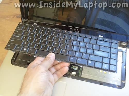
STEP 11.
Remove seven screws from the bottom of the laptop.
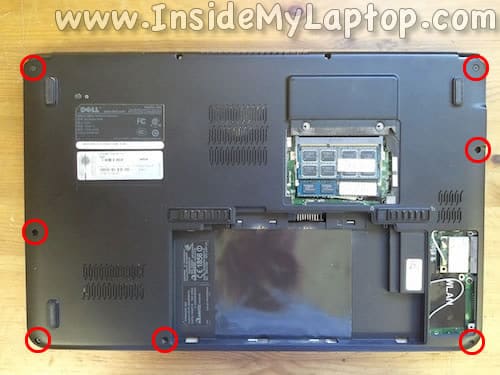
STEP 12.
Remove six screws securing the top cover.
Disconnect the touchpad cable.
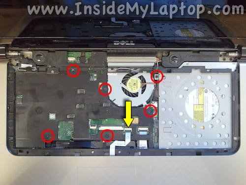
Here’s how to disconnect the cable.
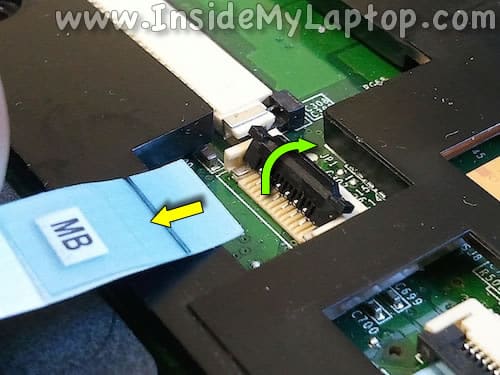
STEP 13.
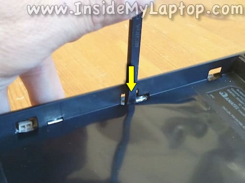
In the battery compartment you will find four tabs securing the palm rest to the bottom cover.
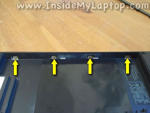
Push on tabs with a plastic stick to disengage them.
STEP 14.
Start separating the palm rest from the bottom cover.
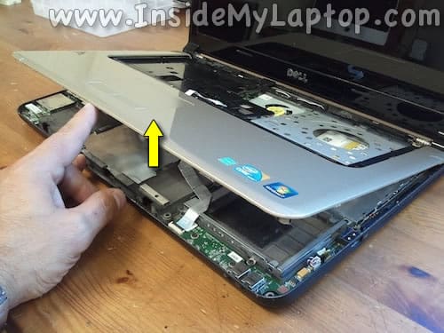
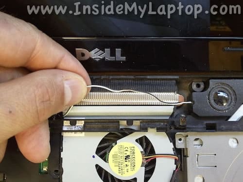
Don’t forget to un-route the speaker cable from the palm rest assembly.
It’s located just above the fan.
STEP 15.
Remove the palm rest assembly.
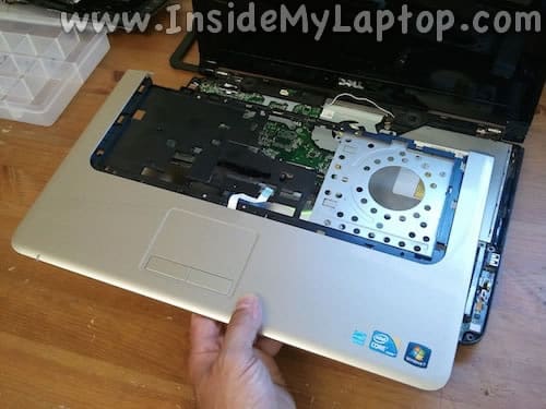
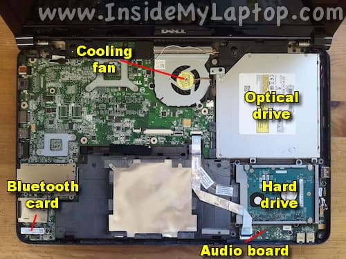
Now you can access and remove the following internal components:
– Cooling fan.
– Optical drive.
– Hard drive.
– Bluetooth card.
– Audio/USB board.
STEP 16.
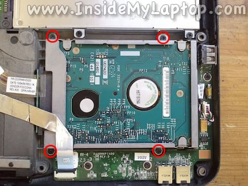
Remove four screws securing the hard drive caddy.
STEP 17.
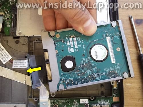
Lift up the hard drive assembly from the laptop case and disconnect the SATA cable.
Now you can replace or upgrade the hard drive if necessary.
I recommend replacing this regular 2.5″ SATA hard drive to a 2.5″ SATA solid state drive. Doing so will improve the laptop performance significantly.
STEP 18.
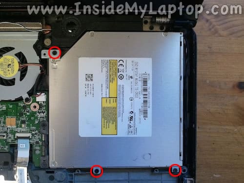
Remove three screws securing the optical DVD drive.
STEP 19.
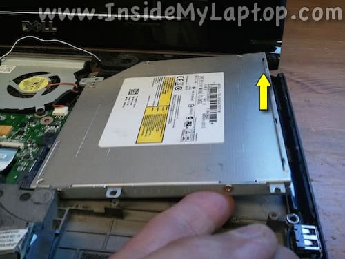
Lift up the right side of the optical drive.
STEP 20.
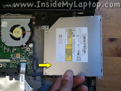
Pull the optical drive to the right to disconnect it from the motherboard.
STEP 21.
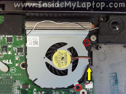
Remove two screws securing the cooling fan.
Disconnect the fan cable from the motherboard.
STEP 22.
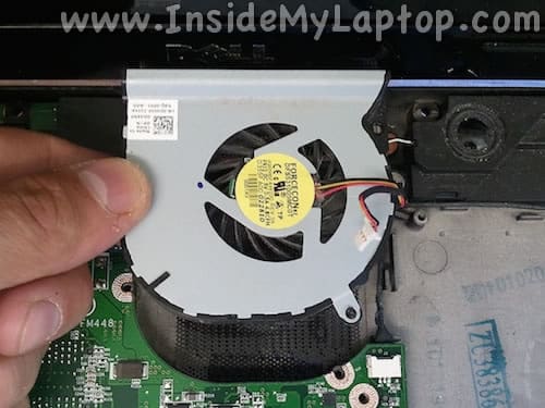
Remove the fan.
Now it can be replaced or cleaned up.
STEP 23.
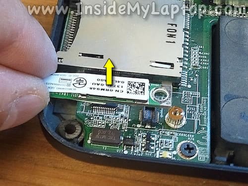
Remove one screw securing the Bluetooth card.
Lift up the card to disconnect it from the motherboard.
Jeff
Thank You 🙂
John
Nice work. My hard drive crashed this weekend. Sad to hear I have to disassemble the entire thing to get to my hard drive.
Matt
Well done! I replaced my drive with a SSD. It would have been a nightmare without these detailed steps.
Paul Watson
I am at step 14 attempting to remove the palm rest. However, the right side (over the optical drive) doesn’t want to separate. I don’t want to pry it off. Any suggestions?
IML Tech
Paul, I don’t remember this unit off the top of my head. Make sure all screws are removed. Check the screws on the bottom and under the keyboard.