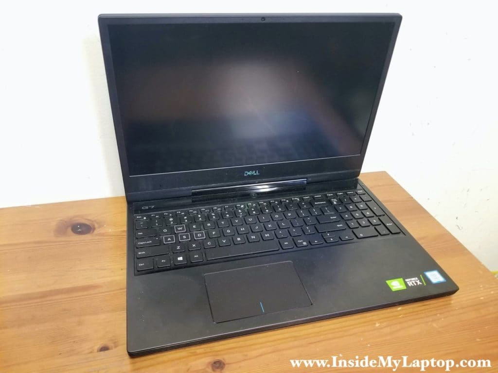
In this guide I show how to disassemble a Dell G7 15 7590 laptop.
At the end of this tutorial I will post a link to the official Dell G7 7590 service manual where you can find more detailed disassembly instructions if needed.
STEP 1.
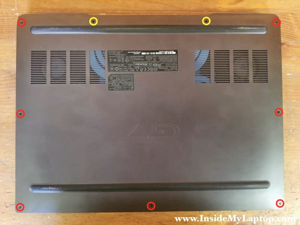
Remove seven screws (red circles) and unscrew two captive screws (yellow circles).
The captive screws will stay attached to the bottom cover.
STEP 2.
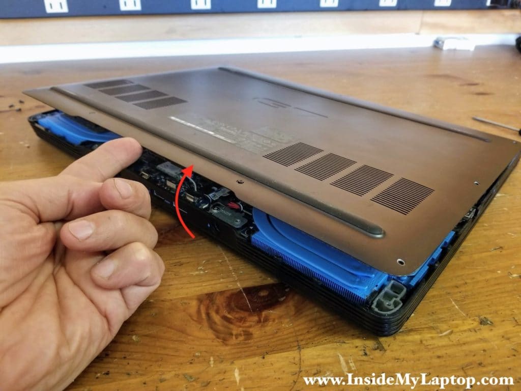
Separate the bottom cover from the rest of the laptop. Start removing the bottom cover from the hinge area.
STEP 3.
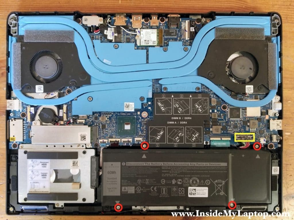
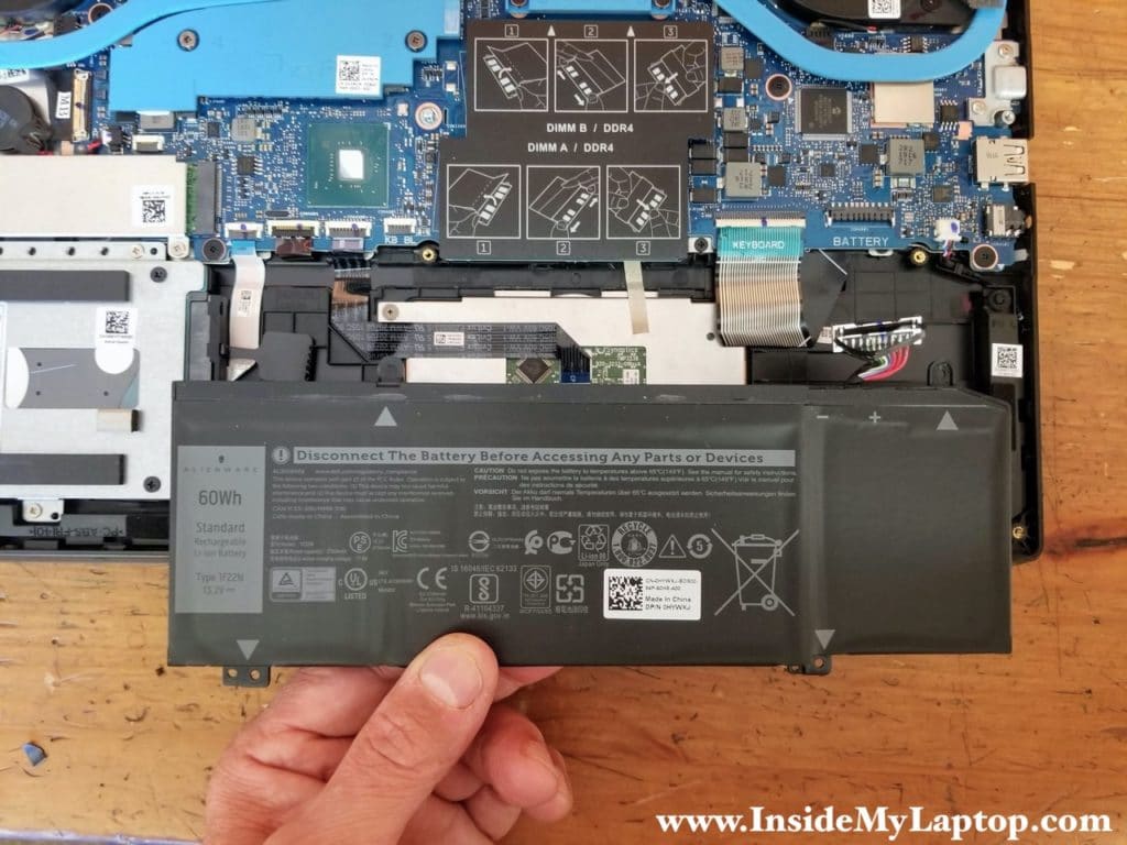
Remove four screws securing the battery and disconnect the battery cable.
STEP 4.
Remove the battery. This is battery type 1F22N.
STEP 5.
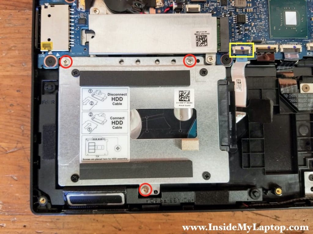
Remove three screws securing the hard drive caddy.
Disconnect the hard drive cable from the motherboard.
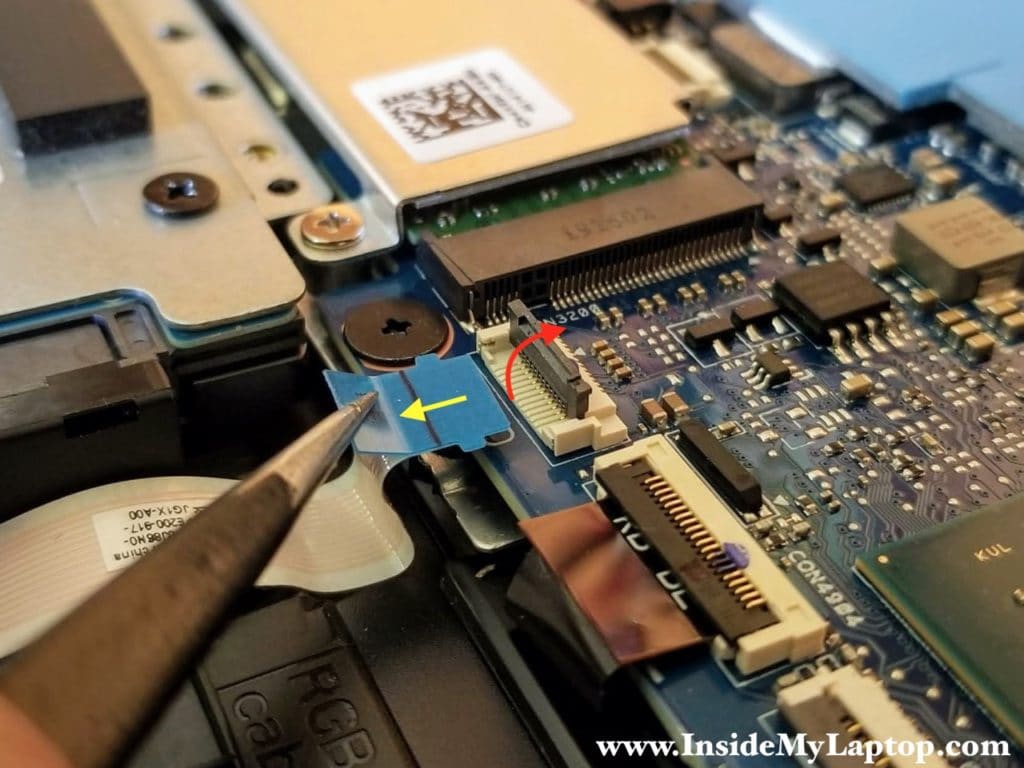
Here’s how to disconnect the hard drive cable.
Unlock the connector by lifting up the locking tab (red arrow) and pull the cable out (yellow arrow).
STEP 6.
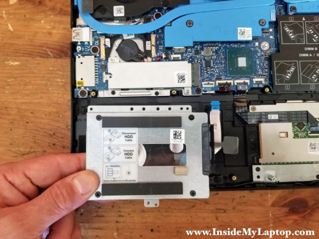
Remove the 2.5″ hard drive with the cable attached. I suggest replacing this hard drive with a 2.5″ solid state drive to improve the perforance.
STEP 7.
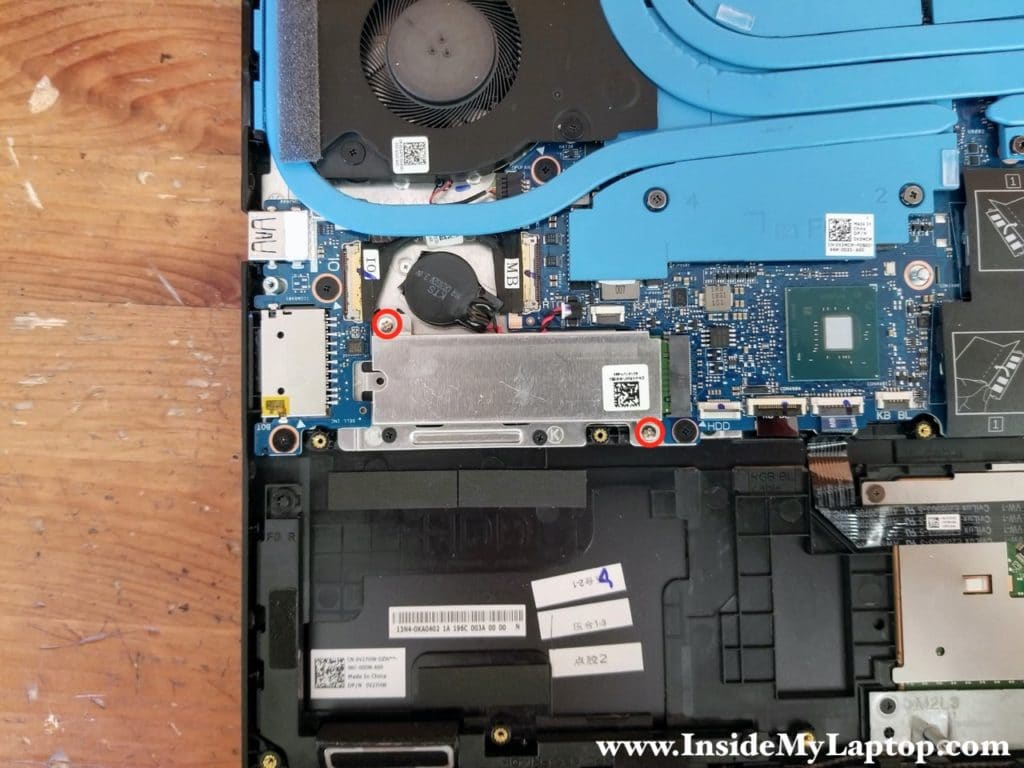
Remove two screw from the SSD cover and remove the cover.
STEP 8.
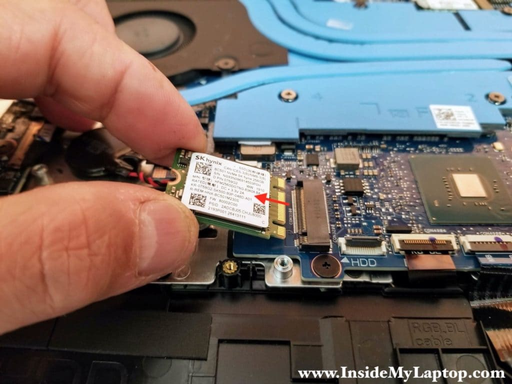
Remove one screw securing the SSD and pull the drive out.
What type of SSD Dell G7 15 7590 supports?
One M.2 2230 solid-state drive PCIe NVMe 3×2 Class 35 Up to 512 GB
One M.2 2280 solid-state drive PCIe NVMe 3×4 Class 40 Up to 1 TB (more common model).
STEP 9.
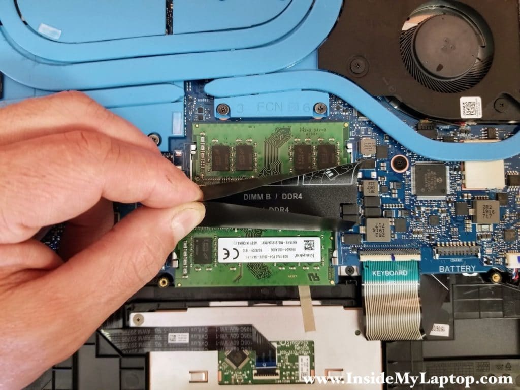
Both memory modules are hidden under the mylar cover. Both memory modules are easily accessible and can be removed and replaced if necessary.
According to Crucial:
Standard Memory: 8GB or 16GB removable
Maximum Memory: 32GB (2 x 16GB) DDR4-3200 SODIMM.
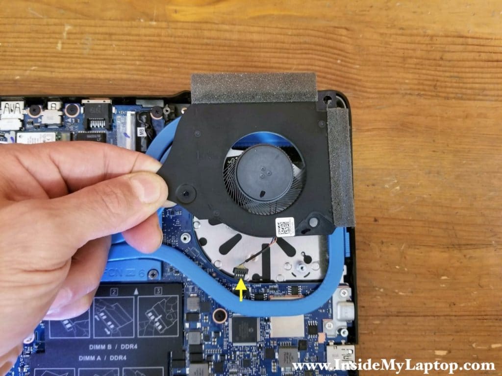
STEP 10.
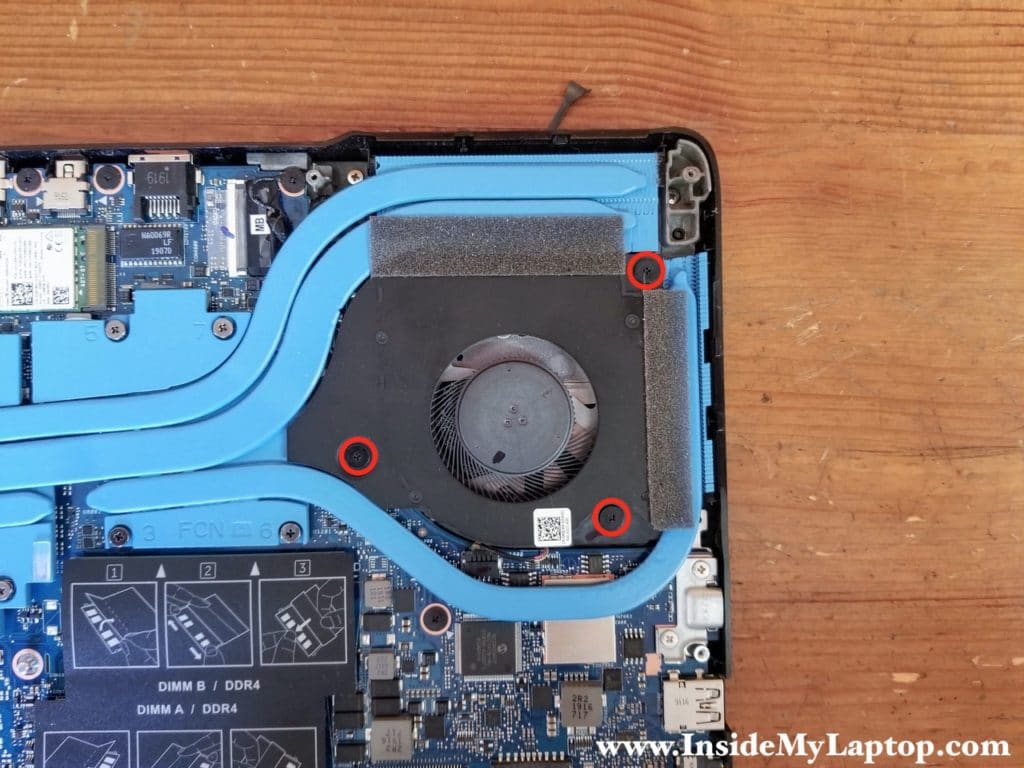
Remove three screws securing the CPU fan.
STEP 11.
Lift up the CPU fan, disconnect the cable from the motherboard and remove the fan.
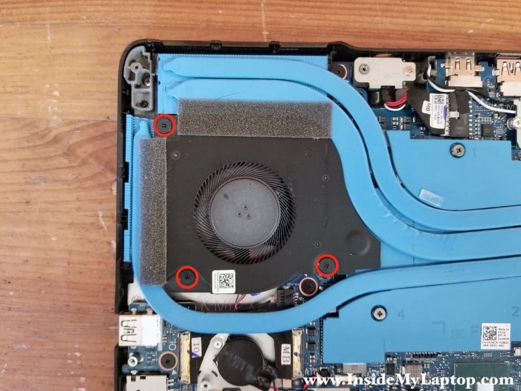
STEP 12.
Remove three screws securing the GPU fan.
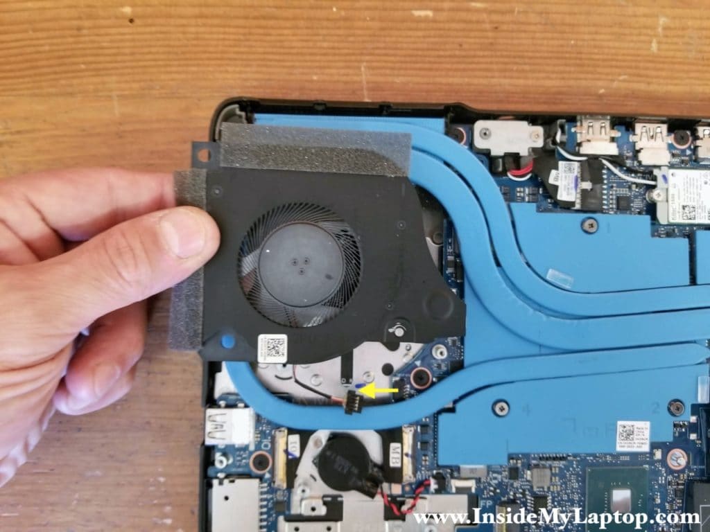
STEP 13.
Lift up the GPU fan, disconnect the cable from the motherboard and remove the fan.
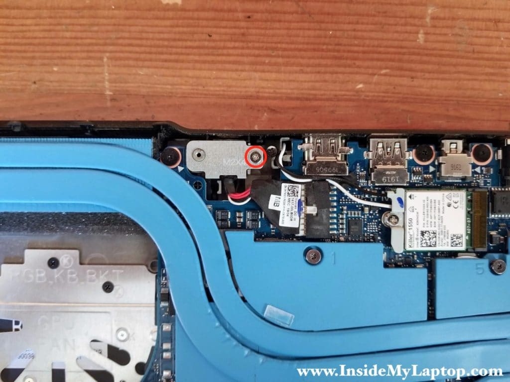
STEP 14.
Remove one screw from the DC power jack cover and remove the cover.
STEP 15.
Unplug the DC power jack cable from the motherboard and remove the DC jack.
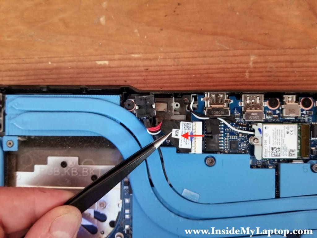
STEP 16.
Remove one screw securing Wi-Fi antenna cables and remove the cover.
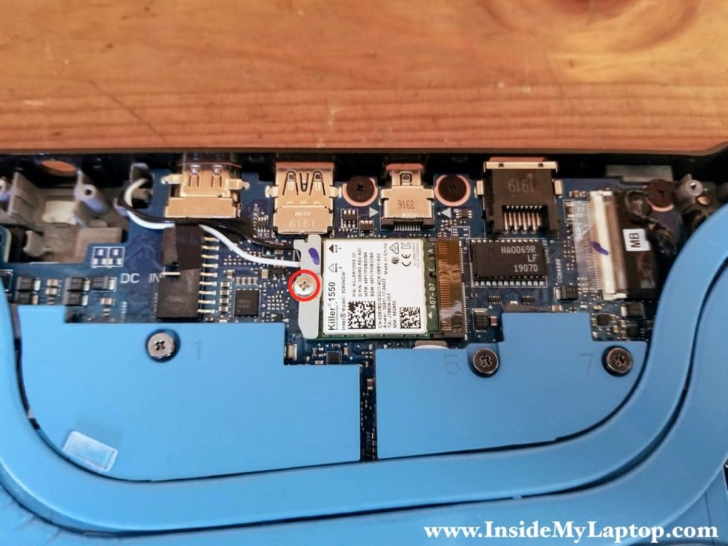
STEP 17.
Disconnect both Wi-Fi antennas from the wireless card.
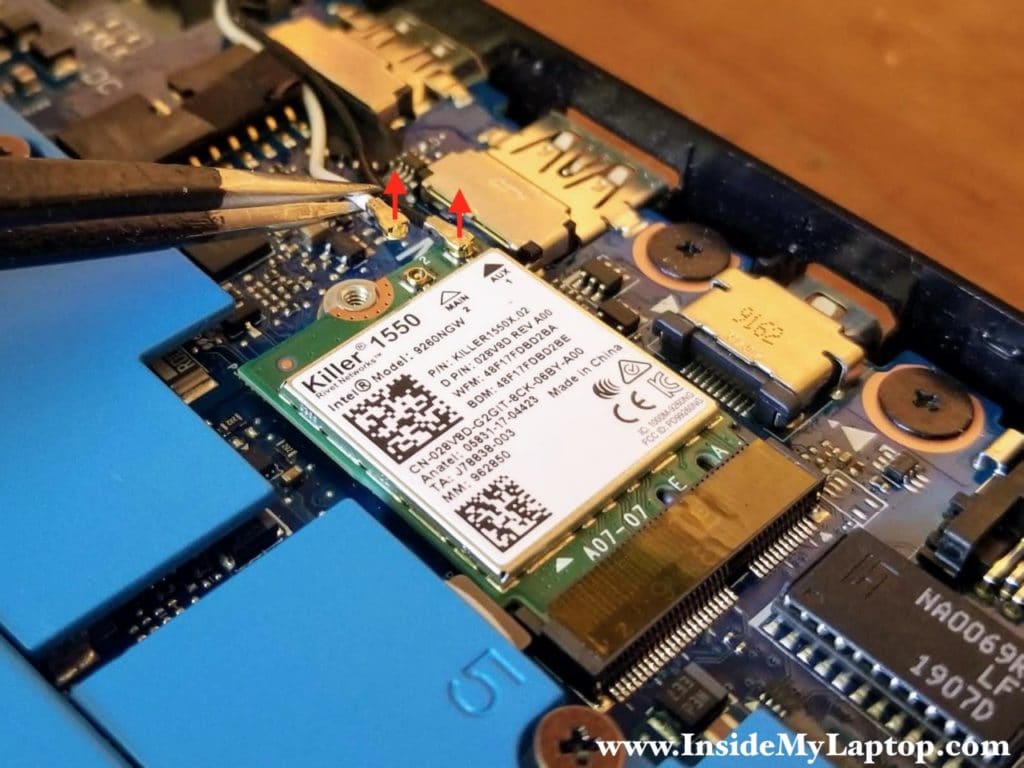
STEP 18.
Pull the wireless card out.
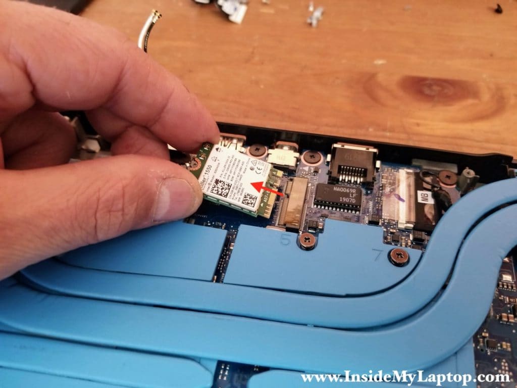
STEP 19.
Remove two screws securing the USB SD card reader board. Disconnect the I/O cable from the motherboard.
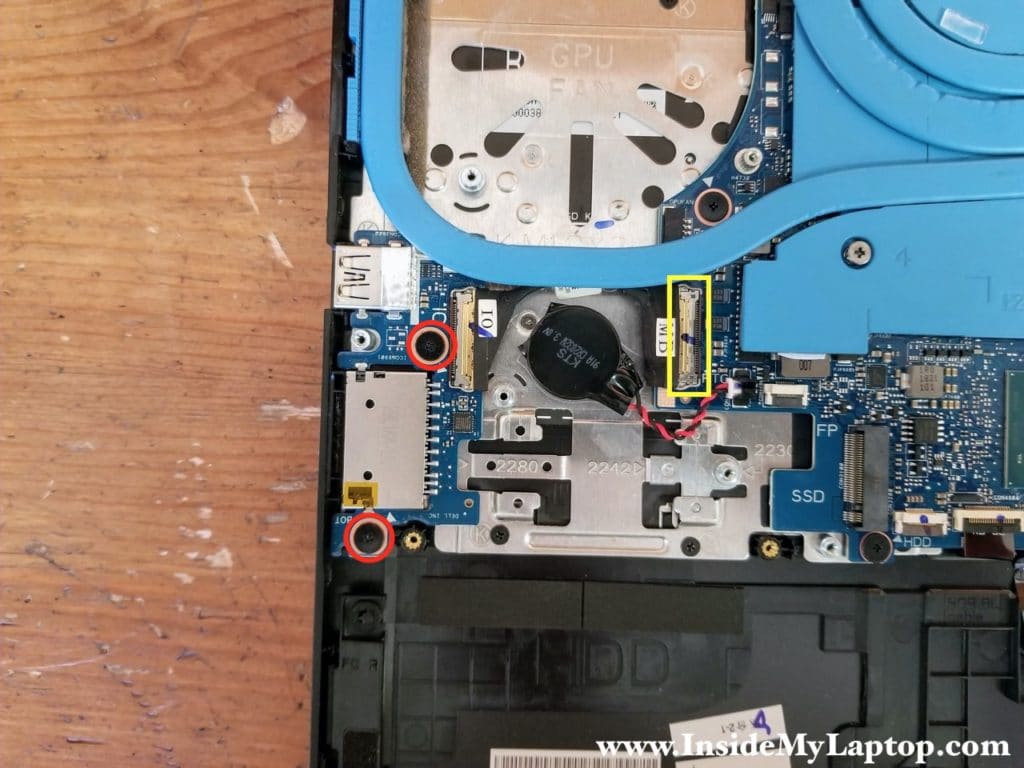
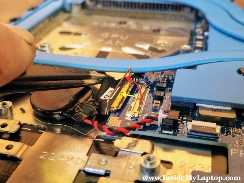
Here’s how to release and unplug the I/O cable.
Unlock the connector by lifting up the metal bracket (red arrow) and pull the cable out (yellow arrow).
STEP 20.
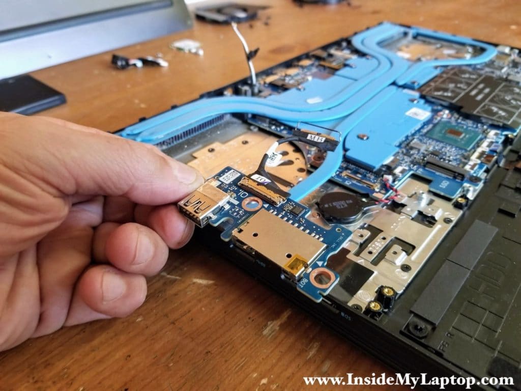
Remove the USB SD card reader board.
STEP 21.
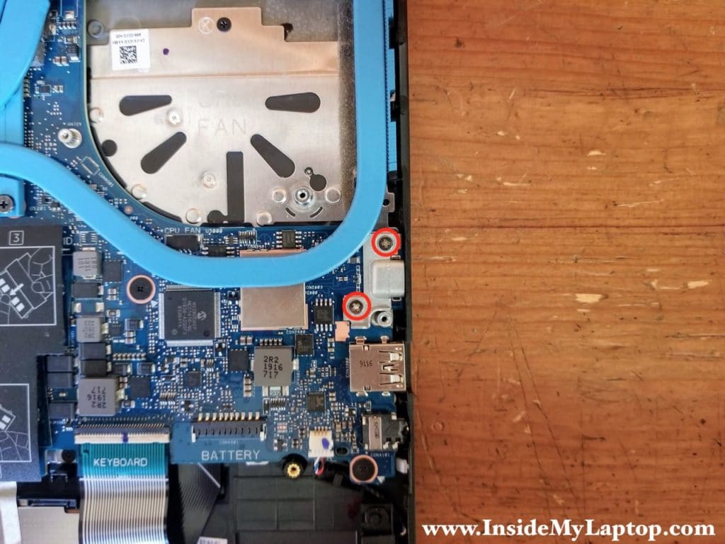
Remove two screws securing the USB-C cover and remove the cover.
STEP 22.
Remove eight screws securing the motherboard.
Disconnect the following color-coded cables:
– Display cable (yellow)
– Keyboard backlight cable (orange)
– Touchpad cable (green)
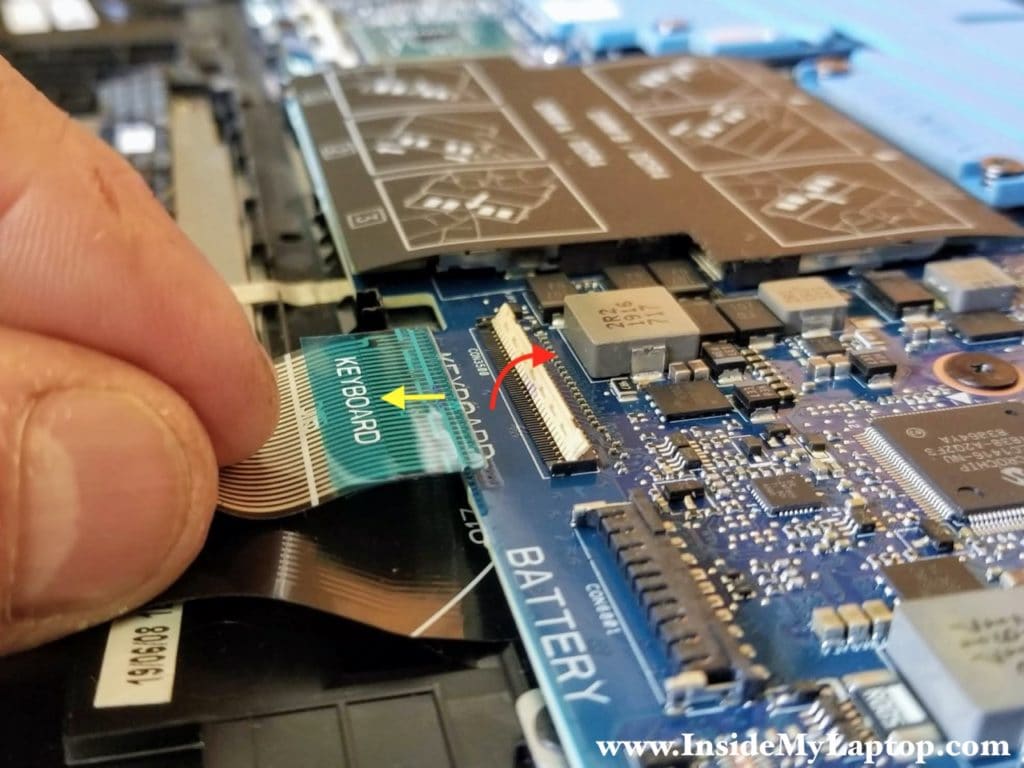
– Keyboard cable (blue)
– Speaker cable (pink)
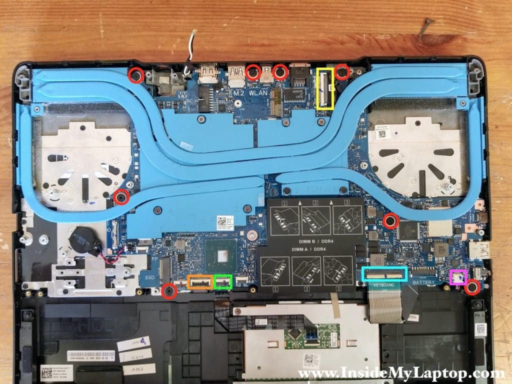
All connectors has to be unlocked before removing the cable.
STEP 23.
Remove the motherboard.
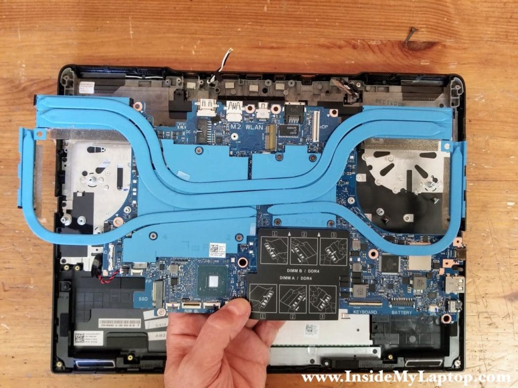
Here’s a photo of the other side of the motherboard.

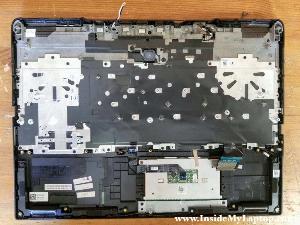
After the motherboard is removed you can access and remove the keyboard.
Doug
What size screwdriver? The screws are ridiculously small.
IML Tech
I’m using Wiha Phillips size PH0.
Brian David
Help!
I cannot get the fan screws out abd the faces are stripping…
I wanted to repaste the CPU and GPU… But now I cannot!
Also… Is there a source to replace these screws?