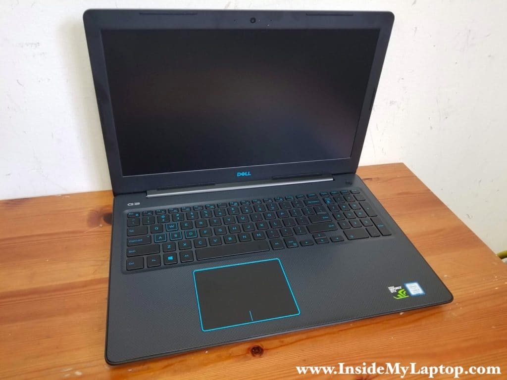
In this guide I show how to disassemble Dell G3 15 3579 model P75F laptop.
I’ll be taking apart the laptop base and removing all major internal components. For the LCD screen replacement please check out my screen replacement guide (follow the link at the end of this post).
Also, at the end of this post you will find a link to the official Dell G3 15 3579 laptop service manual, just in case you need more detailed disassembly instructions.
STEP 1.
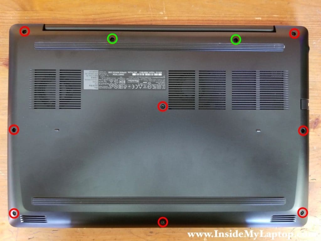
Remove eight screws (color-coded in red) from the laptop base cover.
Loosen two screws (color-coded in green). These two screws will stay attached to the base cover when you remove it.
STEP 2.
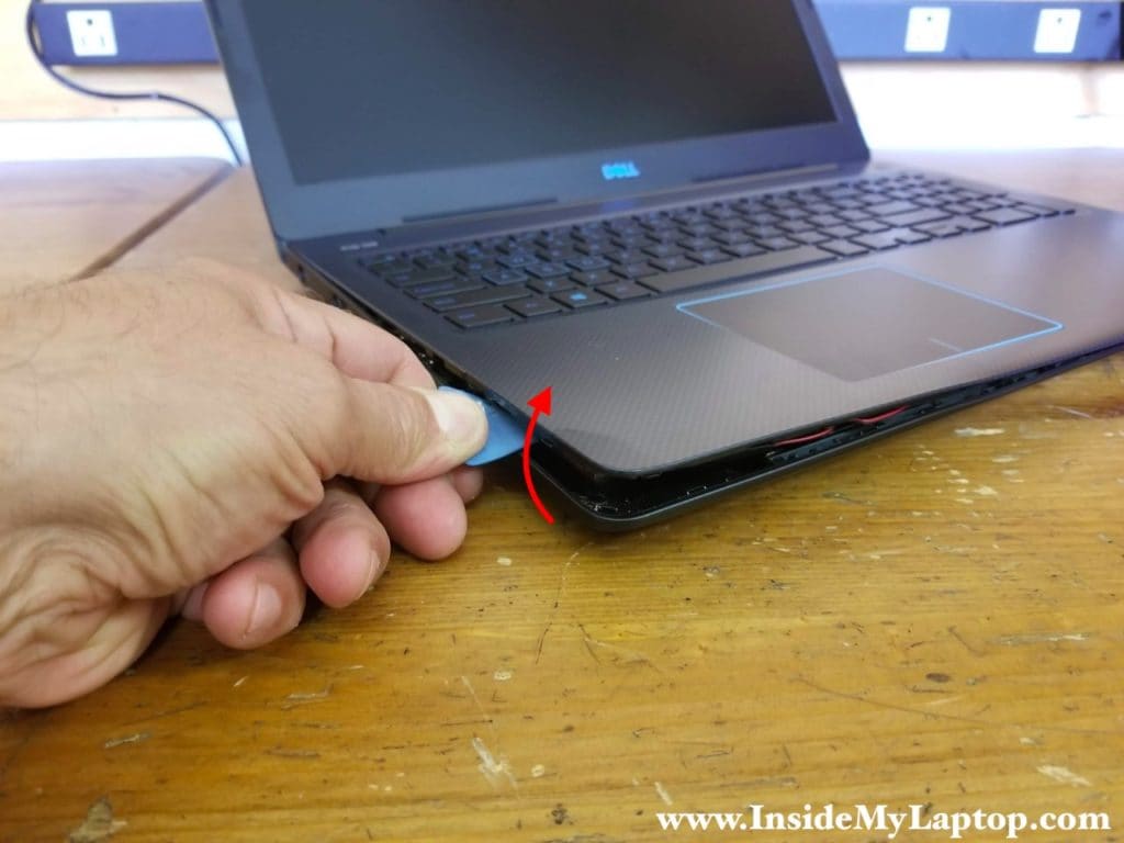
Start separating the palmrest assembly from the base cover using a case opener tool.
Pry the palmrest up to release hidden latches.
STEP 3.
Turn the laptop upside down and remove the base cover.
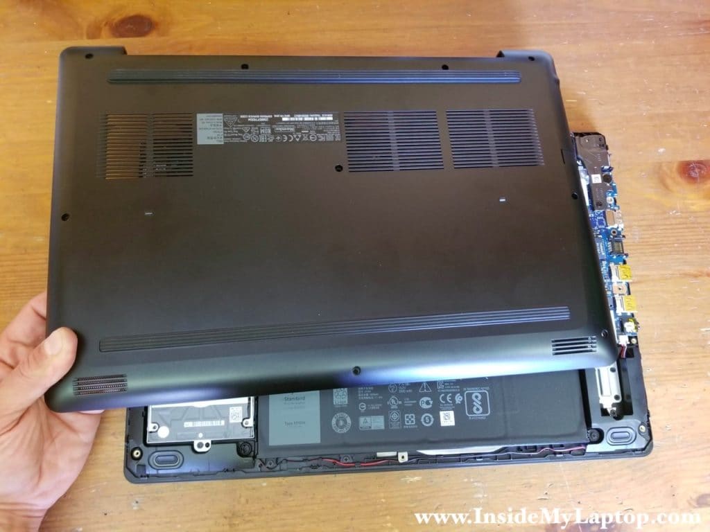
With the base cover removed you can easily access both memory (RAM) slots, the hard drive and both cooling fans.
Standard memory for Dell G3 15 3579 is 8GB or 16GB but it can support up to 32GB (2x16GB) DDR4 2666/3200 SODIMM RAM modules.
STEP 4.
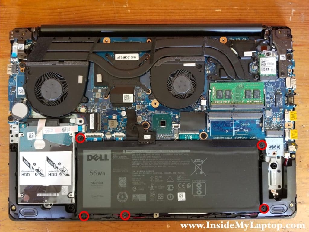
Remove five screw attaching the battery to the frame.
STEP 5.
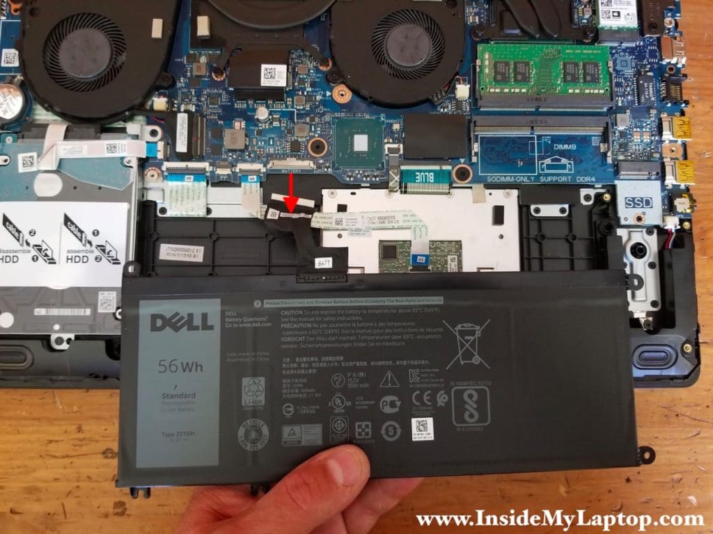
Lift up the battery and disconnect it from the motherboard.
Dell G3 15 3579 battery model: 33YDH.
STEP 6.
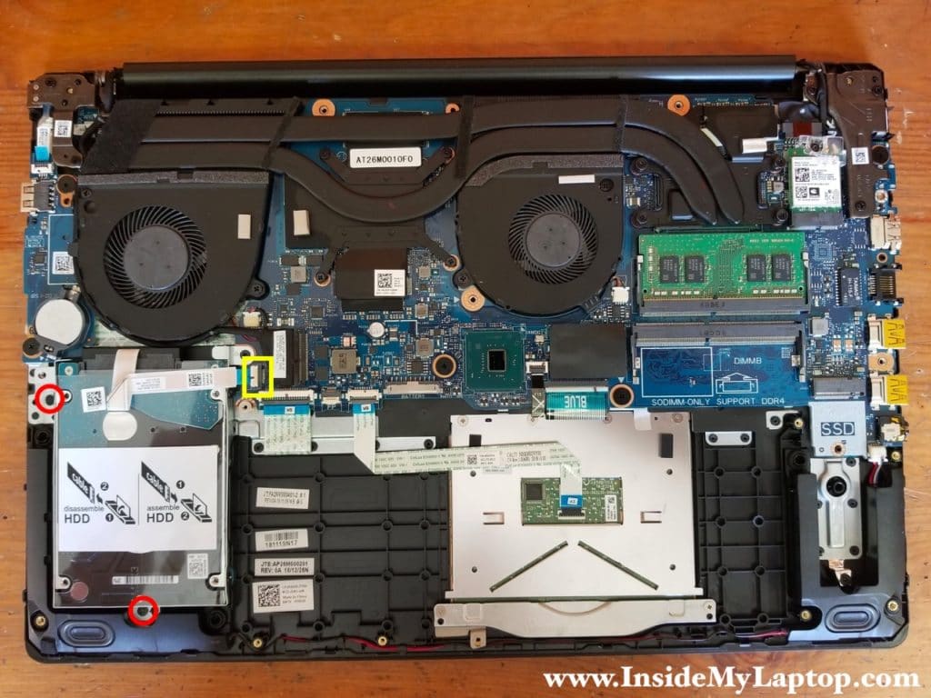
Remove two screws from the hard drive bracket and disconnect the hard drive SATA cable from the motherboard.
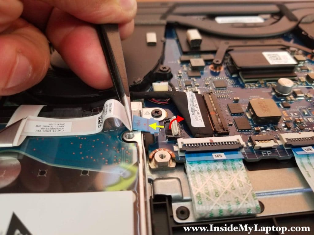
Here’s how to disconnect the hard drive cable:
1. Lift up the connector locking tab (red arrow).
2. Pull the cable out (yellow arrow).
STEP 7.
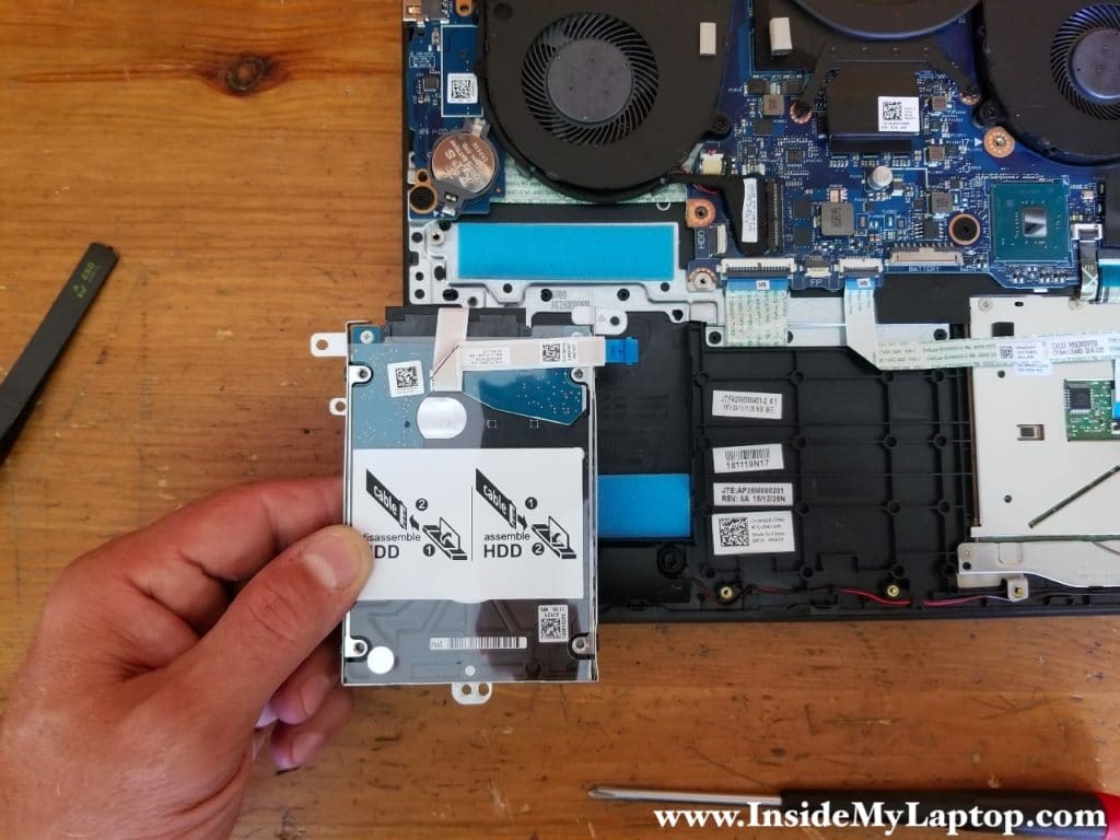
Remove the hard drive assembly with the cable attached.
This particular Dell G3 15 3579 laptop was configured with a regular 2.5″ spinning hard drive. Upgrading this drive to a 2.5″ solid state drive will improve laptop performance significantly.
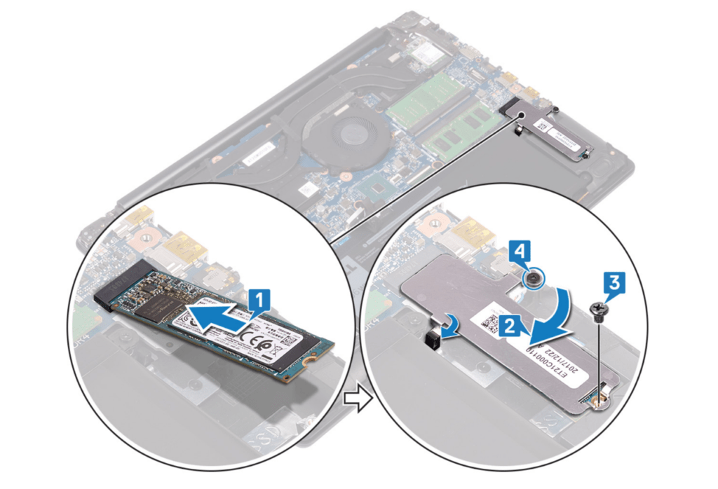
This laptop also has a PCIe slot for an NVMe M.2 SSD. This is an optional upgrade and not all Dell G3 15 laptops have M.2 SSD installed. In order to install the SSD you’ll need a special shield.
Here’s a quote from the Dell service manual:
NOTE: Solid-state drive shield is available only on computers shipped with NVMe solid-state drive.
My opinion: I think this shield is not mandatory. Just find the right screw to secure the SSD to the case and it should be good enough.
STEP 8.
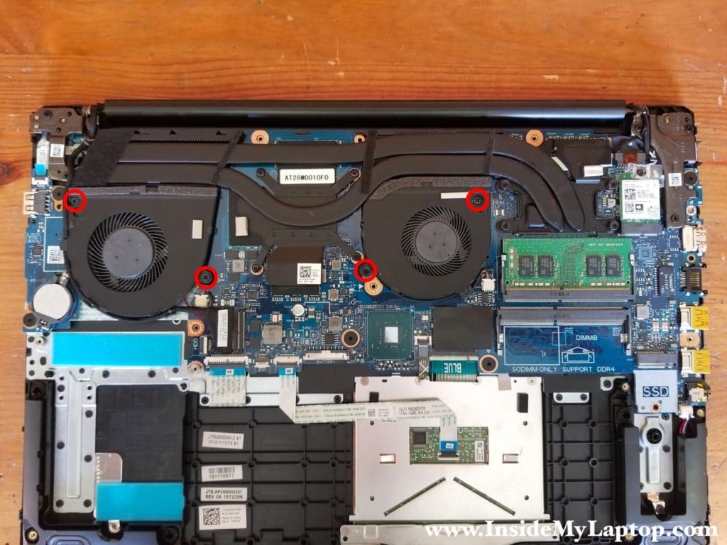
Each cooling fan secured by two screws.
Remove screws securing the left and the right fans.
STEP 9.
Lift up the right fan and disconnect it from the motherboard.
The display video cable routed in the guided path on the side of the fan. You’ll have to unroute the video cable while removing this fan.
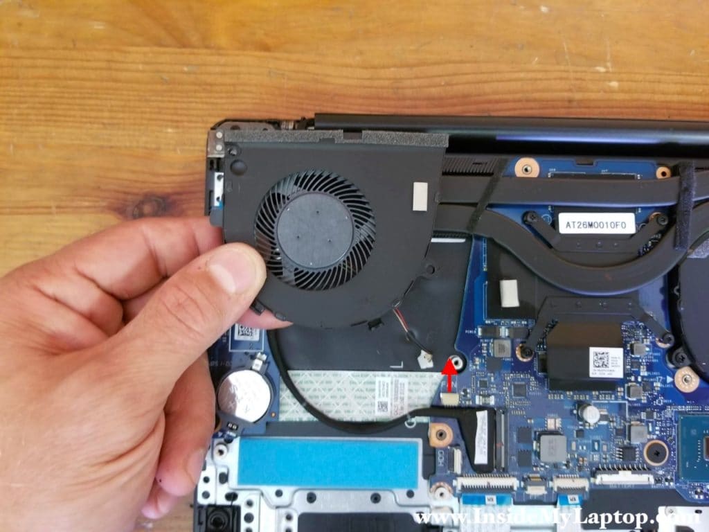
STEP 10.
Lift up the left cooling fan and disconnect it from the motherboard.
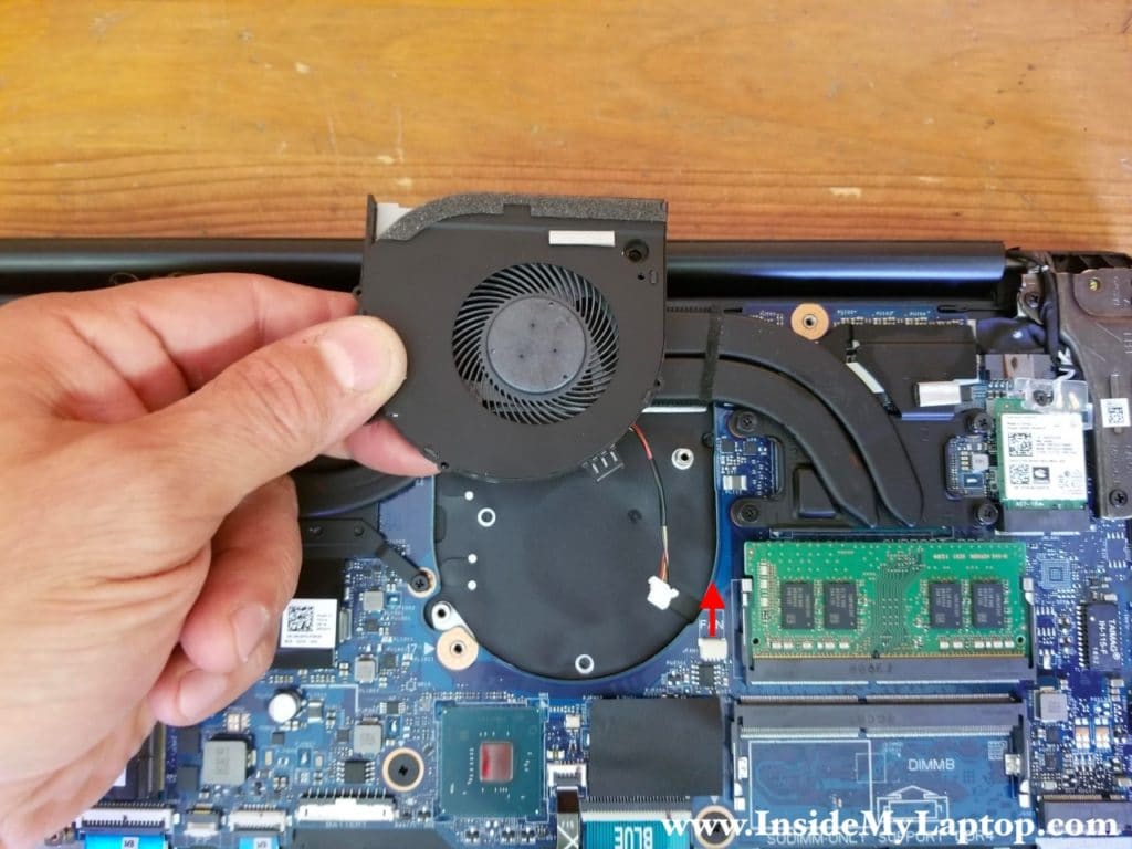
STEP 11.
Remove one screw from the wireless card.
Remove the plastic cover securing both antenna cables.
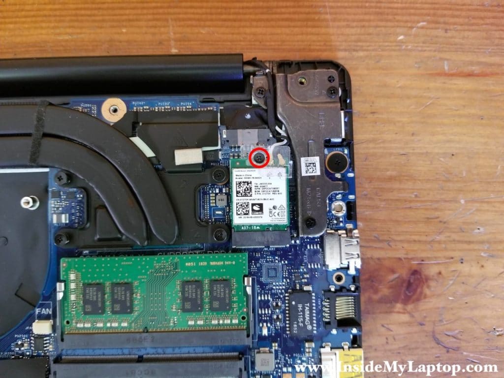
STEP 12.
Unplug the black and the white antenna cables from the wireless card.
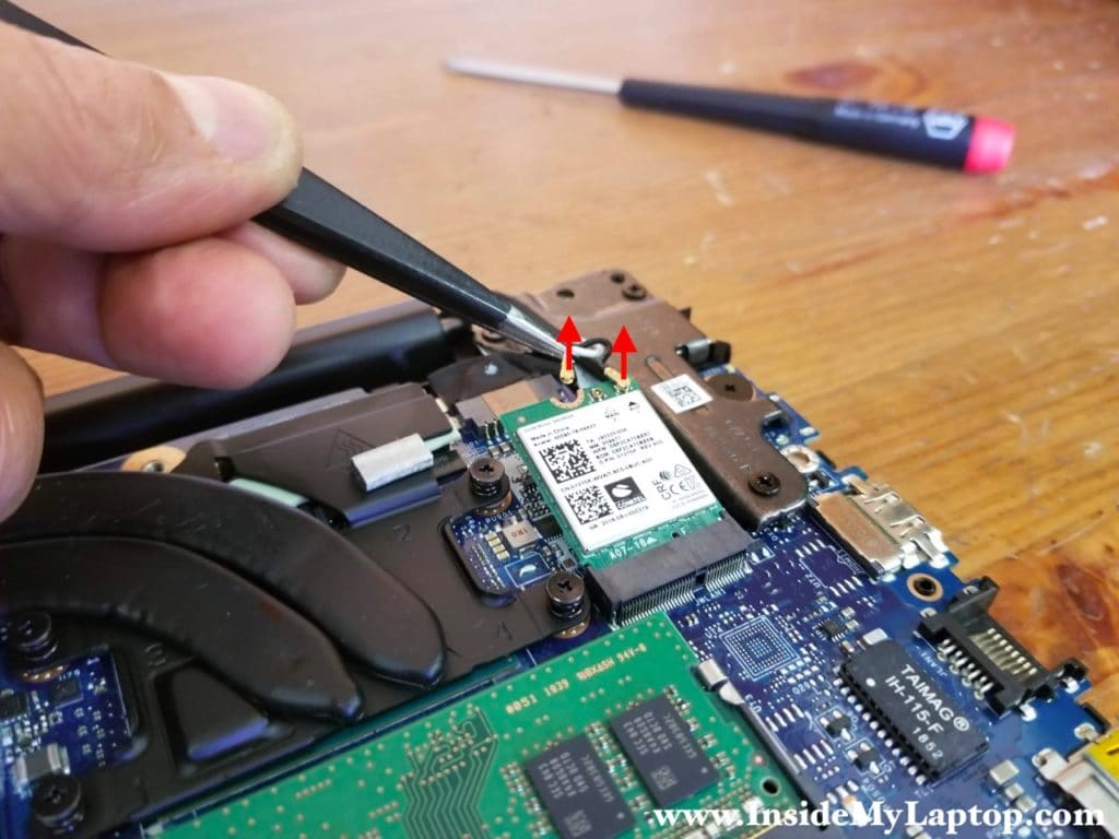
STEP 13.
Remove the wireless card.
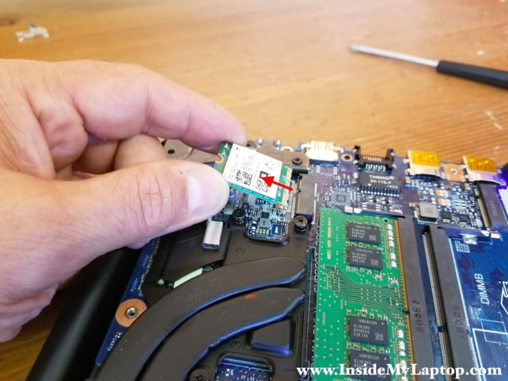
STEP 14.
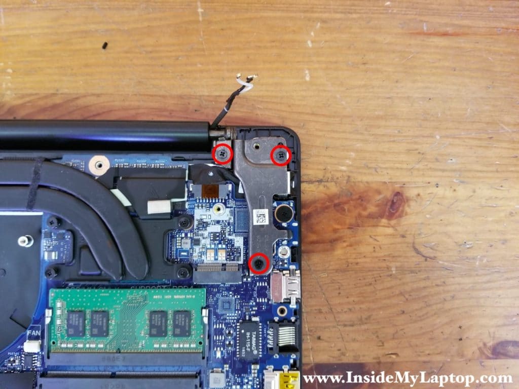
The DC power jack mounted under the left display hinge.
Remove three screw securing the hinge.
STEP 15.
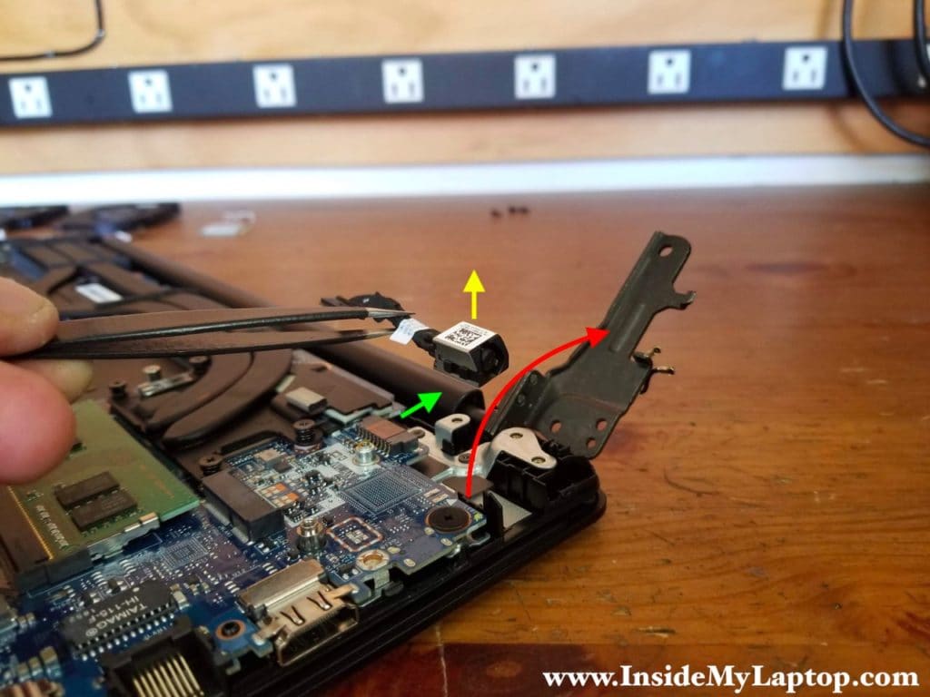
Open the left display hinge as it shown on the following picture.
Disconnect the DC power jack cable from the motherboard (green arrow) and remove the DC jack (yellow arrow).
STEP 16.
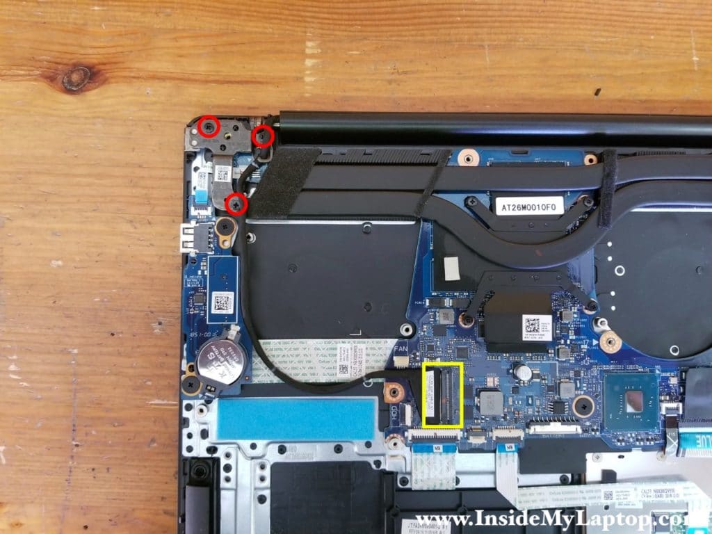
Remove three screws securing the right display hinge.
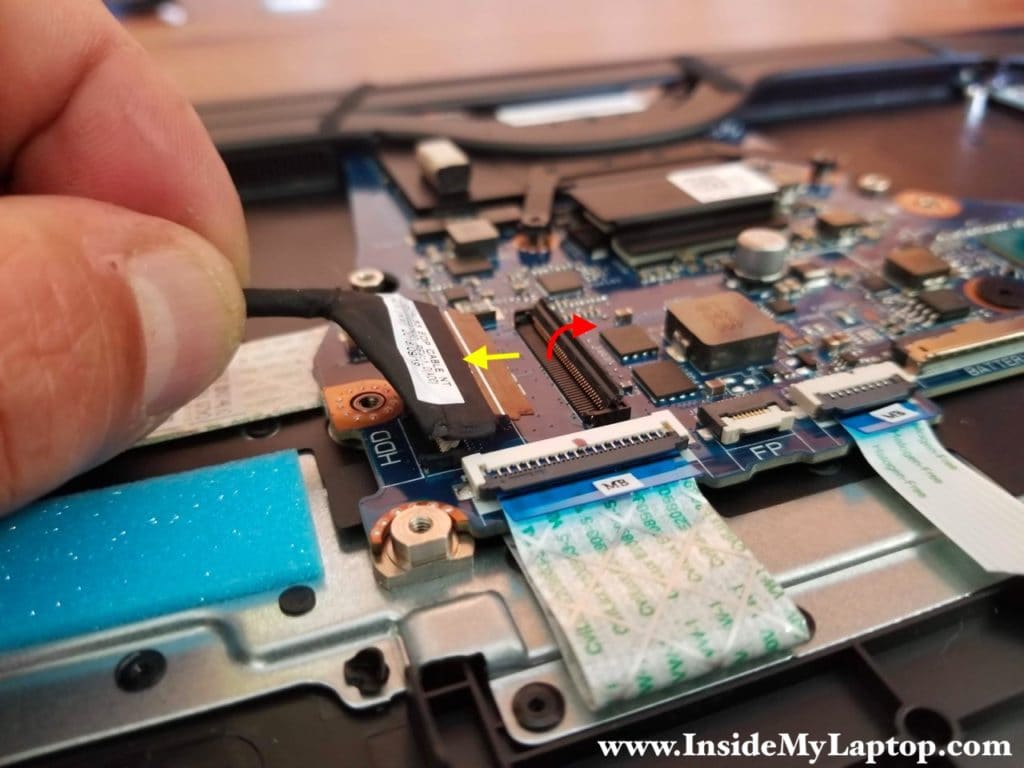
Disconnect the video cable from the motherboard.
In order to disconnect the display video cable it’s necessary to unlock the connector first (red arrow).
STEP 17.
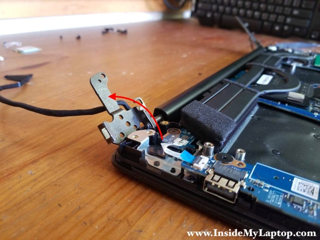
Open up the right display hinge.
STEP 18.
Now you can separate the palmrest assembly from the display panel.
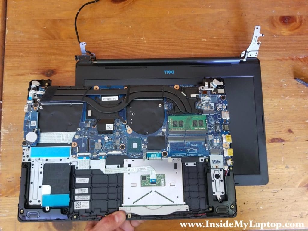
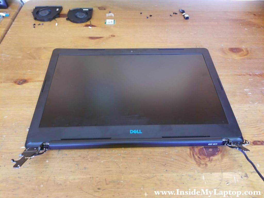
It’s not necessary to separate the display panel from the laptop base in order to remove the screen. It can be done while the display is still attached to the base.
STEP 19.
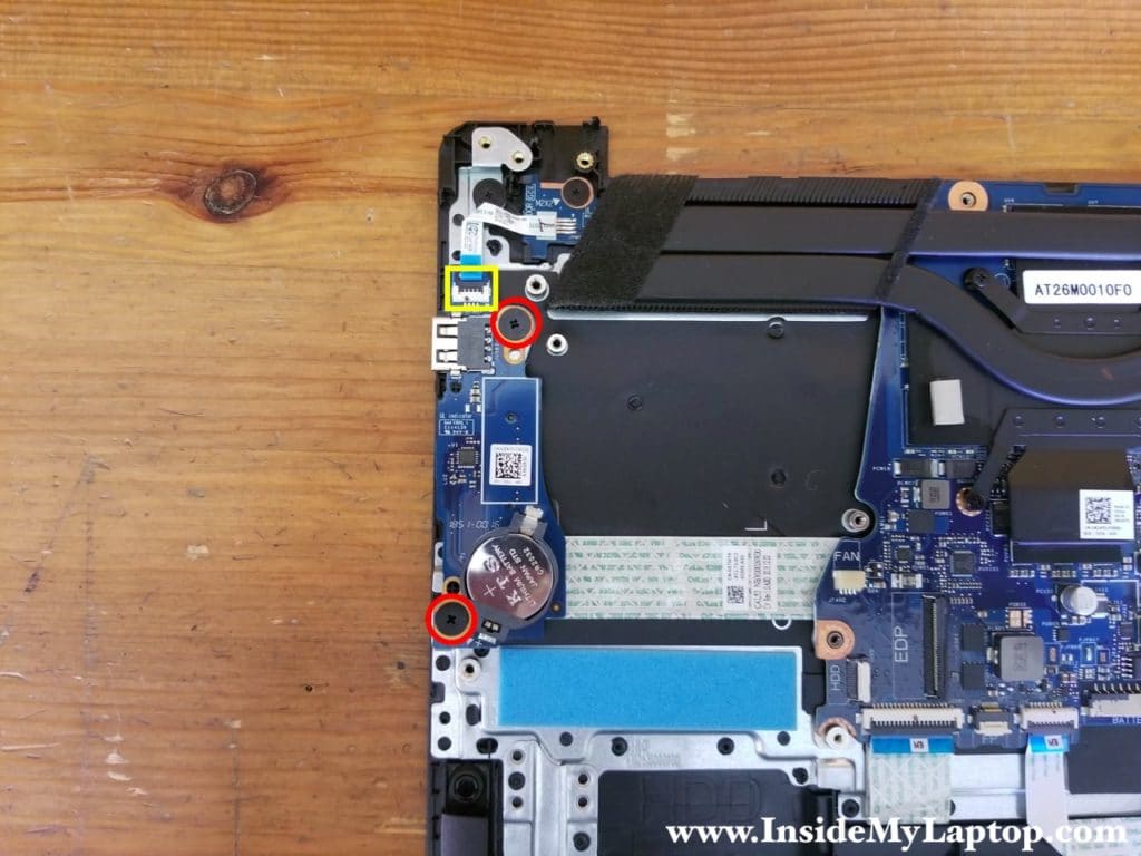
Remove two screws from the USB SD card reader board.
The CMOS battery is attached to this board.
STEP 20.
Lift up the USB SD card reader board and turn it upside down.
Disconnect the I/O cable found on the other side.
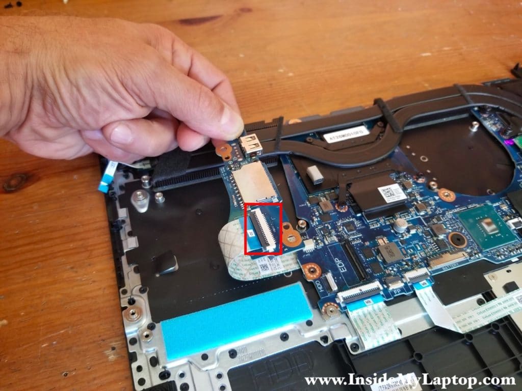
STEP 21.
Remove the USB SD card reader board.
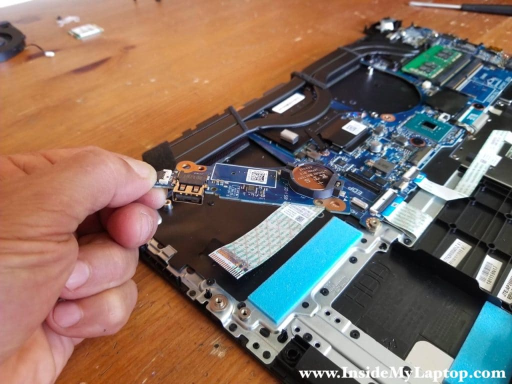
STEP 22.
Remove three screws attaching the motherboard to the palmrest assembly.
Disconnect the following color-coded cables:
– I/O board cable (orange).
– Touchpad cable (yellow).
– Keyboard backlight cable (green).
– Keyboard cable (blue).
– Speaker cable (pink).
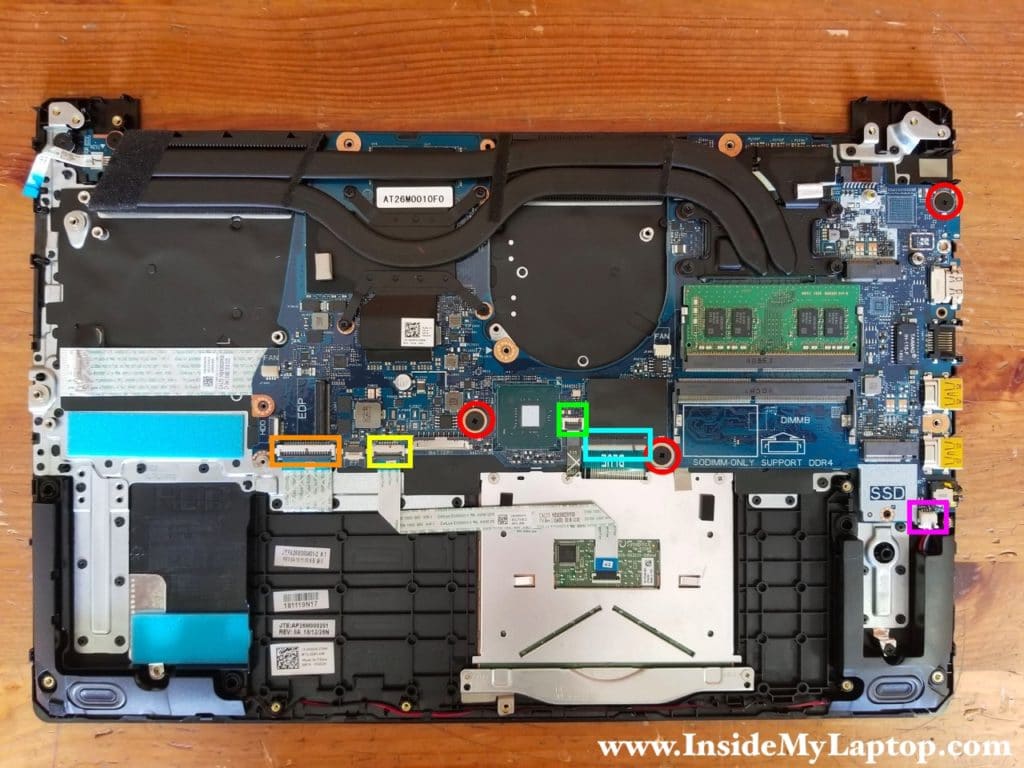
STEP 23.
Separate the motherboard from the palmrest assembly and remove it.
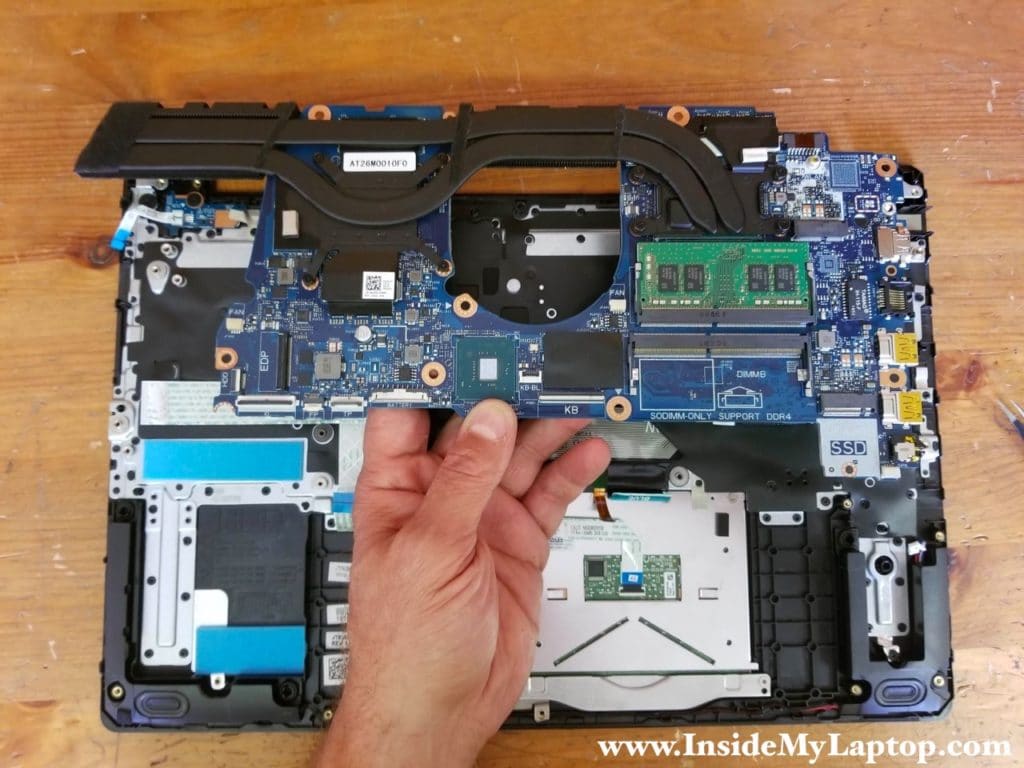
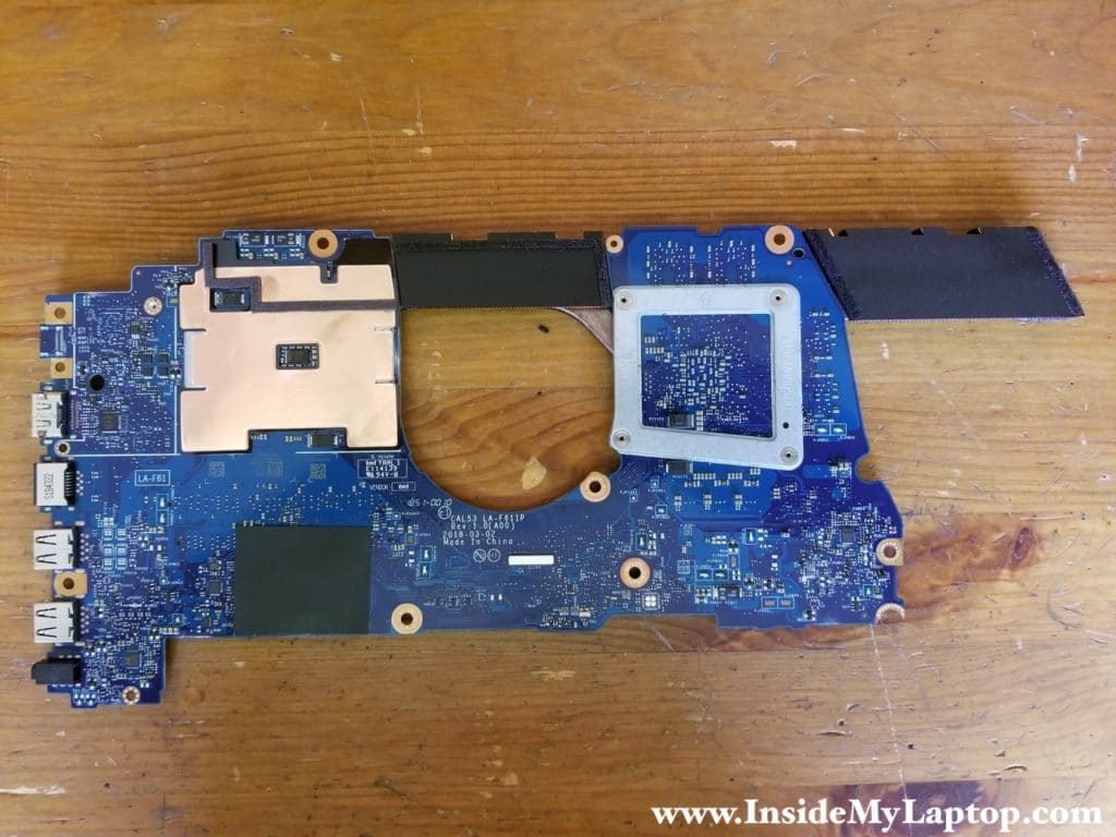
Here’s a photo of the other side of the motherboard.
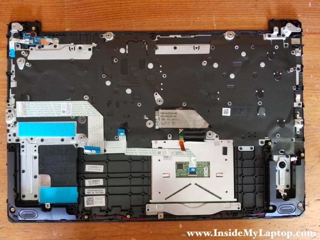
The keyboard in Dell G3 15 3579 laptop is not removable. It’s permanently riveted to the palmrest and hard to replace without replacing the top case.
The touchpad and the power button board, on the other hand, can be easily removed and replaced if necessary.
For the LCD screen replacement instructions please check out this Dell G3 3579 screen removal guide.