In this tutorial I explain how to disassemble an Asus K501U laptop.
In the first part of this guide I will show how to take apart the laptop base assembly in order to access all internal components. In the second part of this guide I will show how to take apart the display panel in order to remove the LCD screen.
Taking apart Asus K501U base assembly
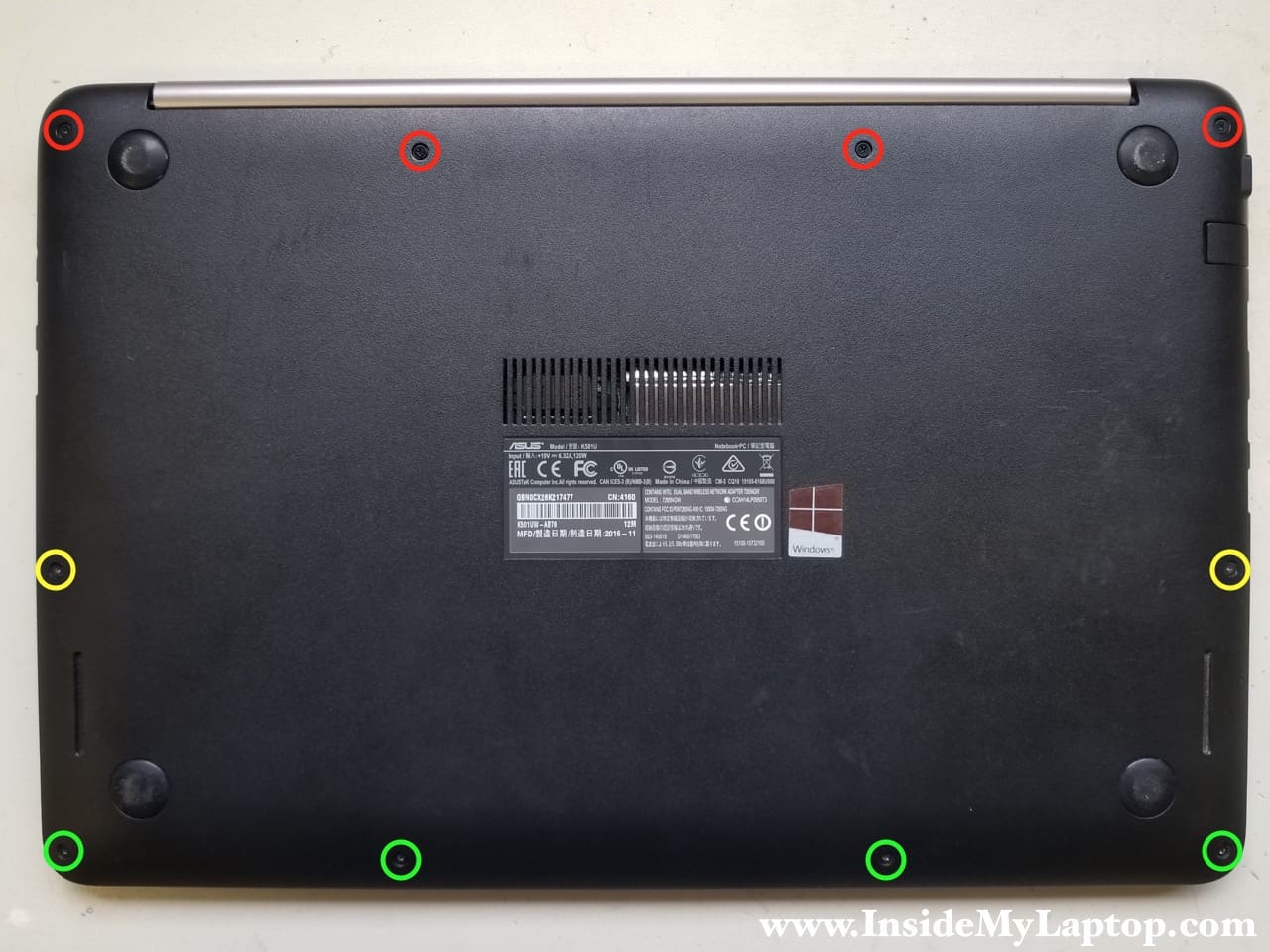
STEP 1.
Remove all shown screws from the bottom cover. These screws have different length. I color-coded screws with similar length in red, yellow and green. Make sure to install them correctly when you assemble the laptop back together.
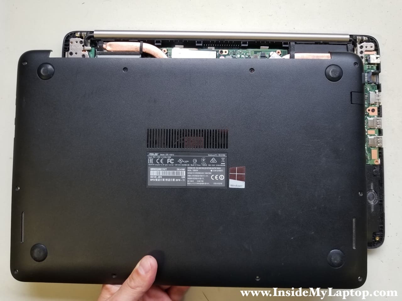
STEP 2.
Separate the bottom cover from the palmrest assembly and remove it.
STEP 3.
Remove four screws securing the battery.
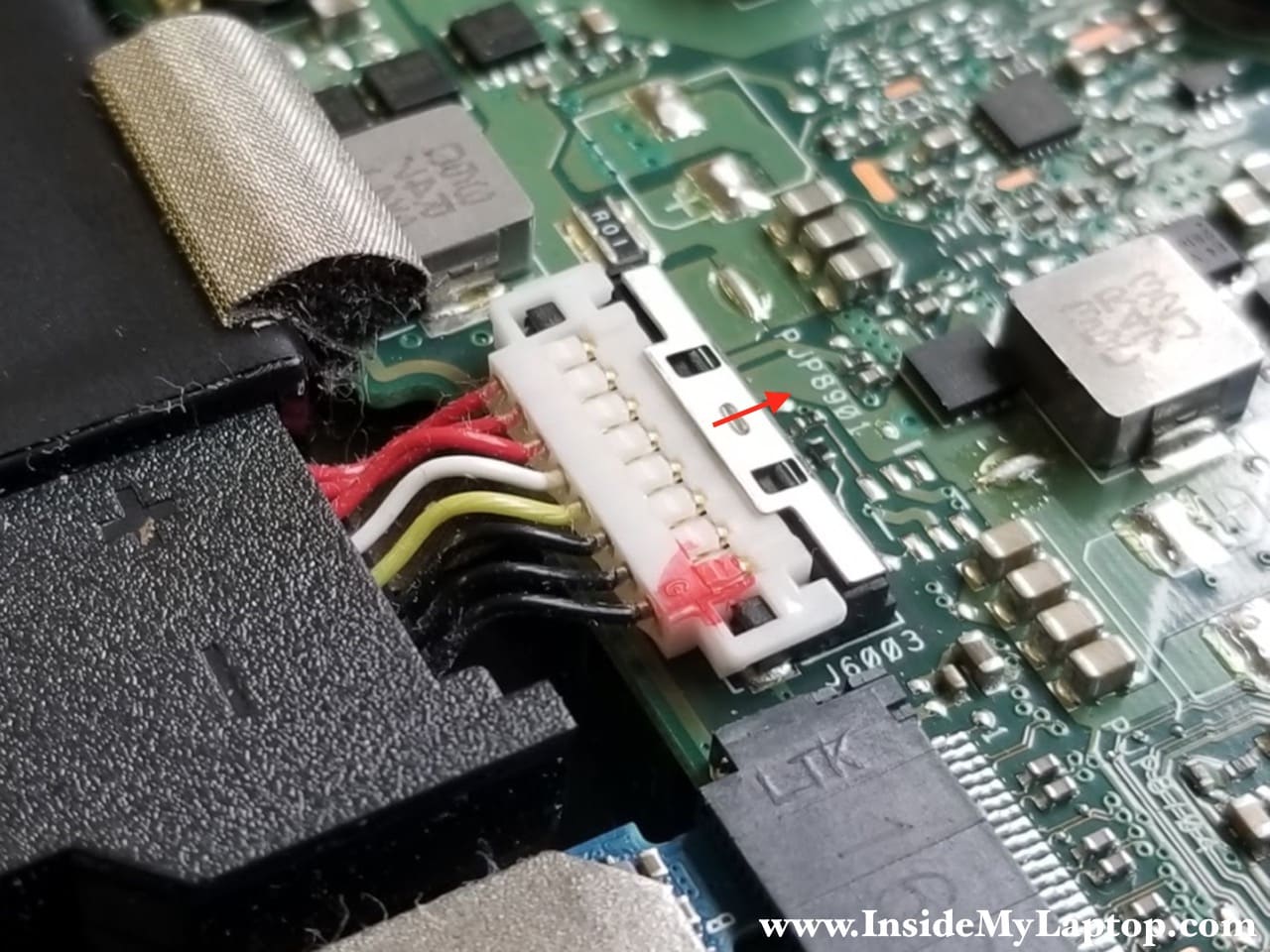
The battery connected to the motherboard via a cable.
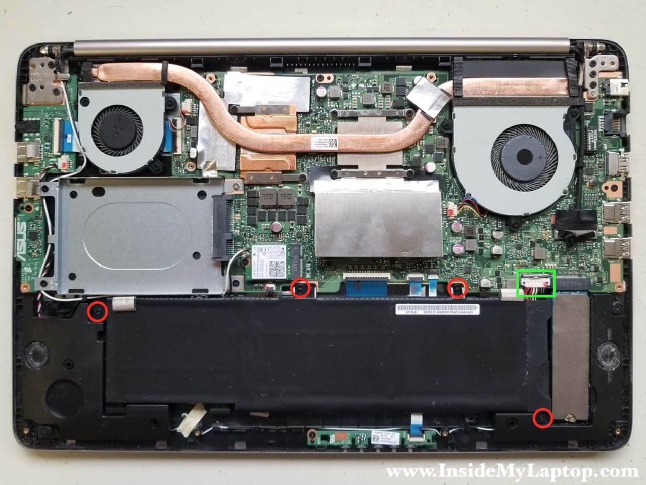
STEP 4.
In order to unlock the battery connector you’ll have to slide the metal bracket to the shown direction.
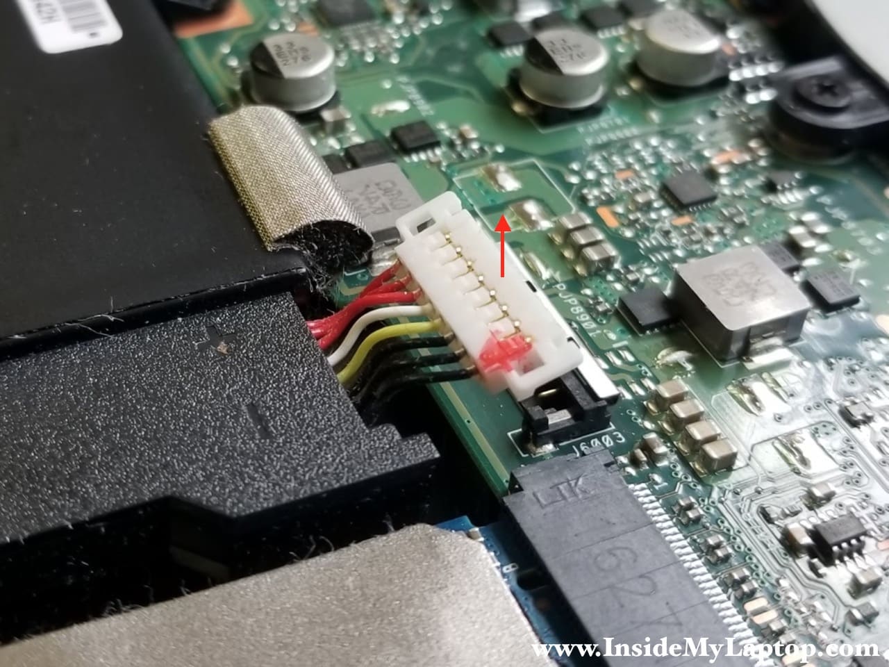
STEP 5.
Carefully lift up the battery cable from the connector.
Do not use metal objects to lift up the cable. You can short metal pins inside.
STEP 6.
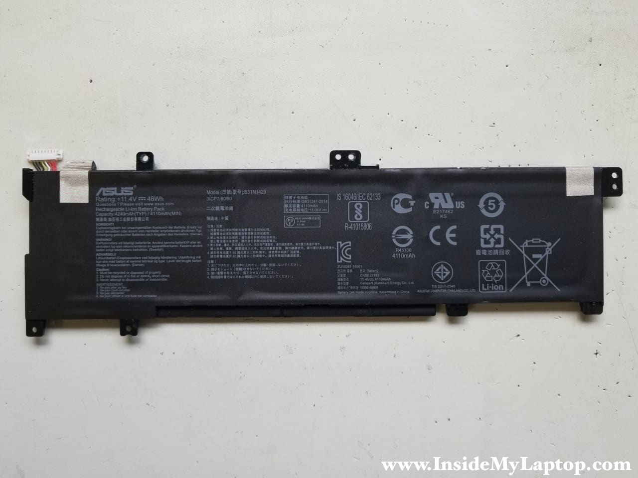
You can find a new replacement battery using the part number printed on the original battery. I would recommend using a genuine Asus battery, not a third-party replacement.
Replacement battery model B31N1429.
STEP 7.
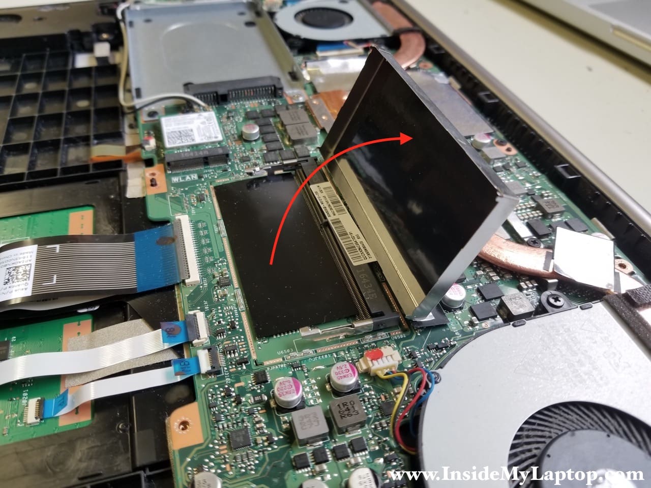
Asus K501U motherboard has only one memory slot. Some memory is built into the motherboard. You can access the available slot if you remove the metal cover.
You can install up to 8GB DDR3-12800 SODIMM RAM module into this slot.
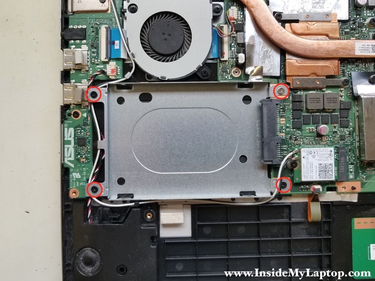
STEP 8.
Remove four screws from the hard drive caddy and remove the caddy. This laptop came with a m.2 solid state drive so there is no regular 2.5″ hard drive installed.
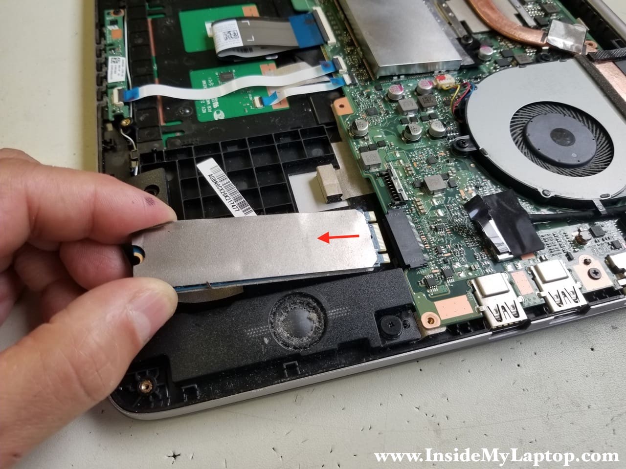
STEP 9.
Remove one screw securing the solid state drive and pull the drive out.
This is m.2 SATA III solid state drive (not NVMe).
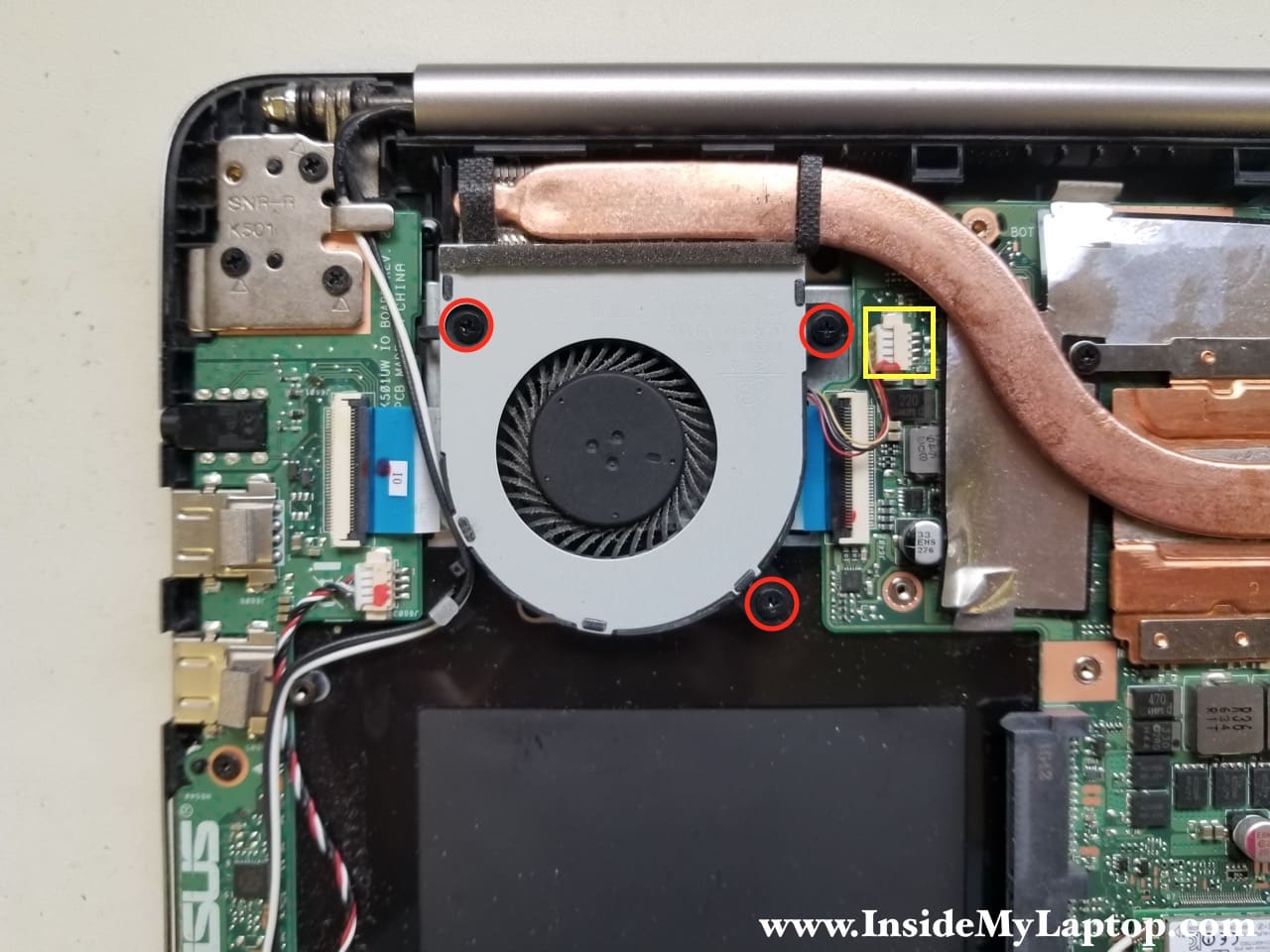
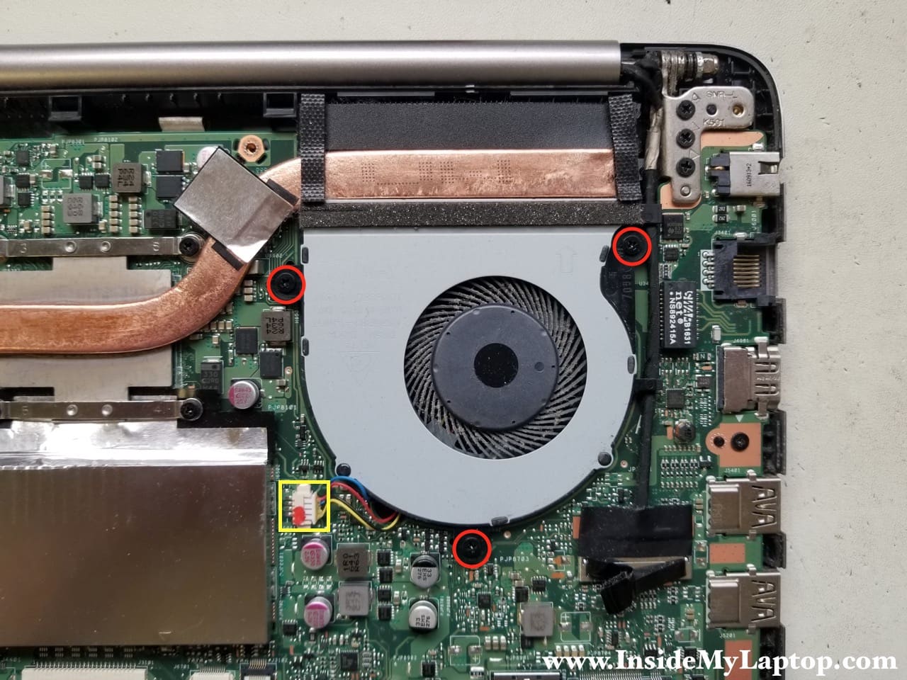
STEP 10.
Remove three screws securing the right fan.
Disconnect fan cable from the motherboard.
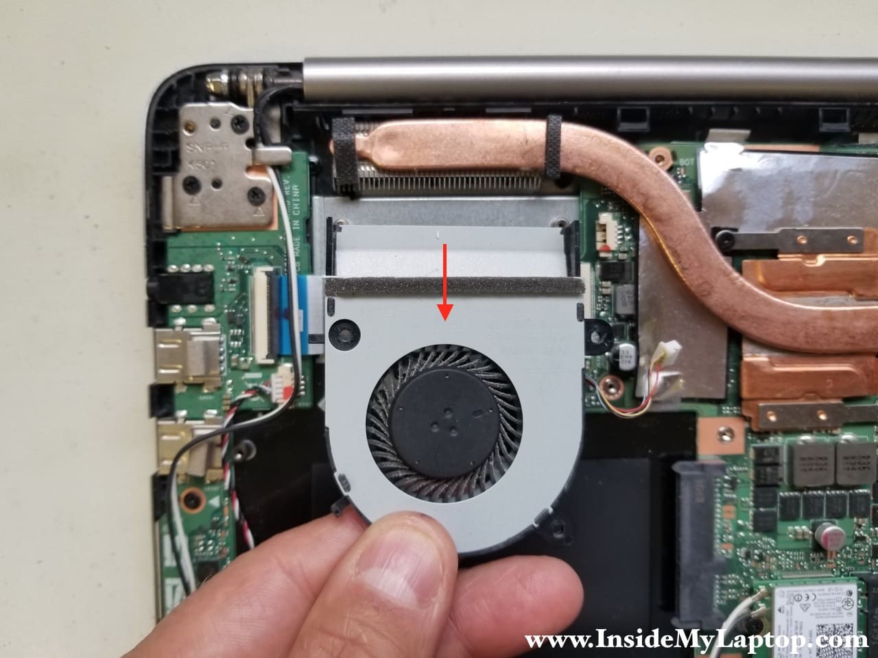
STEP 11.
Remove the right fan.
STEP 12.
Remove three screws securing the left fan.
Disconnect fan cable from the motherboard.
STEP 13.
Remove the left fan.

STEP 14.
The USB audio board is mounted under the right hinge.
Remove three screws from the right hinge.
Remove one screw securing the board.
Disconnect the USB audio board cable (color-coded in green).
Disconnect the right speaker cable (color-coded in yellow).

Here’s how to disconnect the flat cable.
Unlock the connector first by lifting up the locking tab. After that pull the cable out.

STEP 15.
Lift up the right hinge and remove the USB audio board.

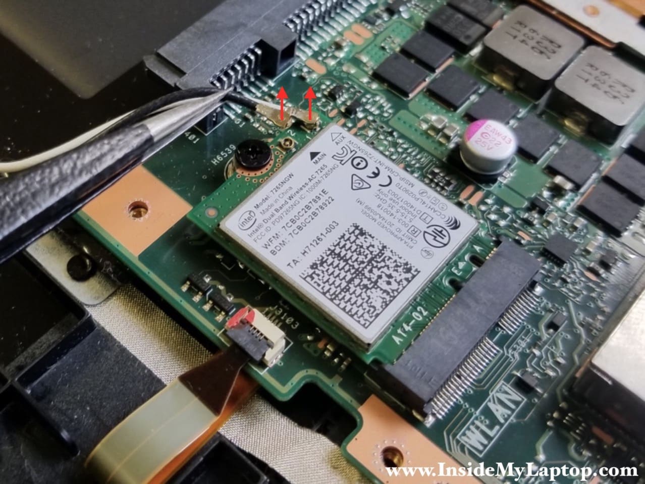
STEP 16.
Carefully disconnect wireless antenna cables from the wireless card.
STEP 17.
Remove one screw securing the wireless card and pull it out.

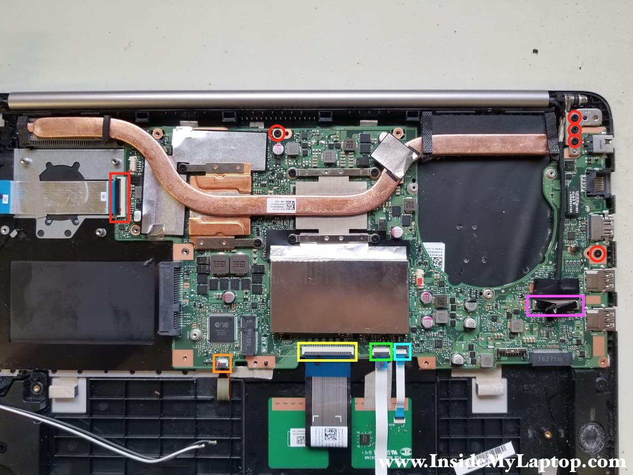
STEP 18.
The motherboard mounted under the left hinge.
Remove three screws from the left hinge.
Remove two screws securing the motherboard.
Disconnect the following cables:
– USB audio bord cable (red)
– Keyboard backlight cable (orange)
– Keyboard cable (yellow)
– LED board cable (green)
– Trackpad cable (blue)
– Display video cable (pink)
STEP 19.
Lift up the left hinge.

STEP 20.
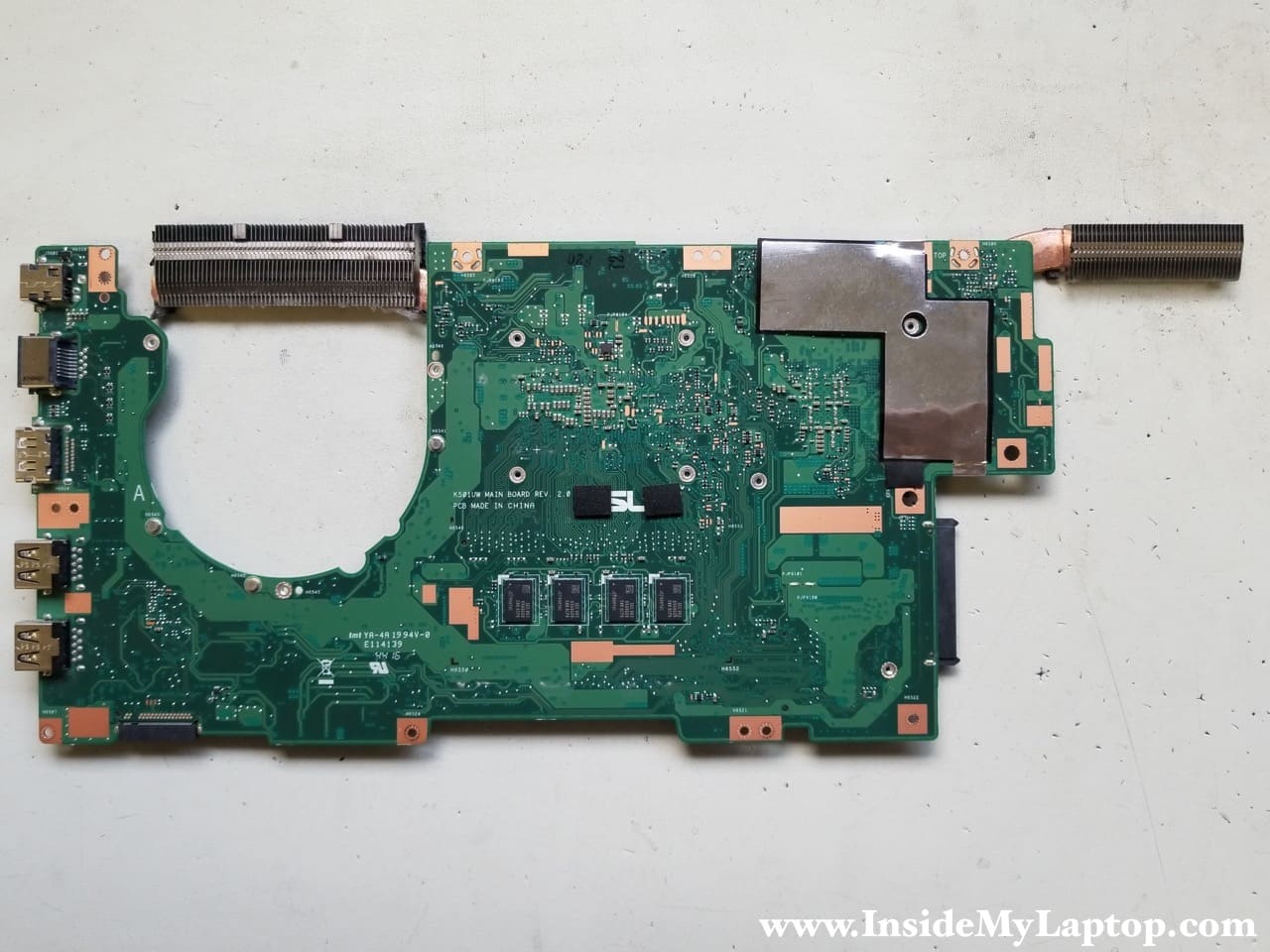
Remove the motherboard.

Here’s the hidden side of the motherboard. The DC power jack is soldered to the motherboard and here’s how to replace the failed DC jack.
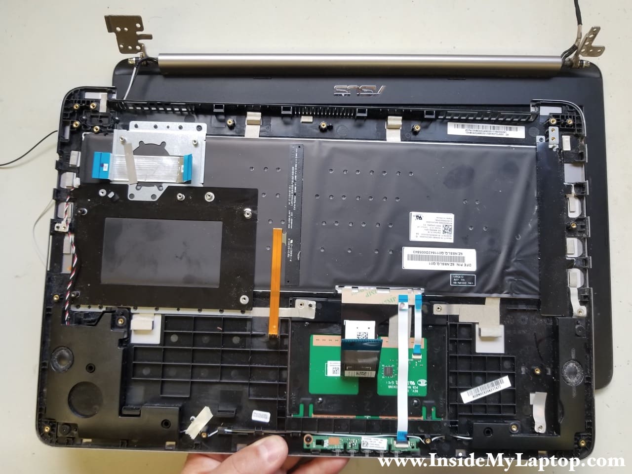
STEP 21.
With both hinges lifted up you can separate the palmrest assembly from the display.
STEP 22.
The trackpad is secured to the palmrest assembly with one screw. Remove the screw.
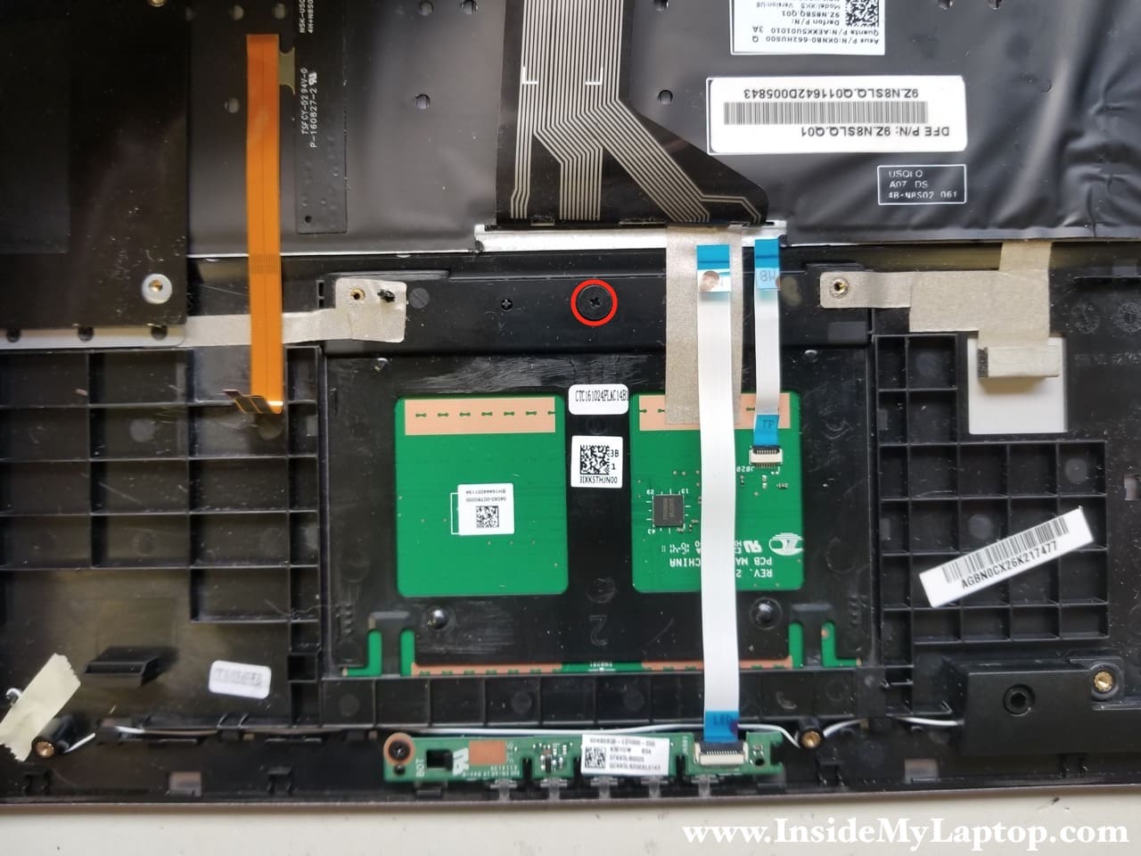
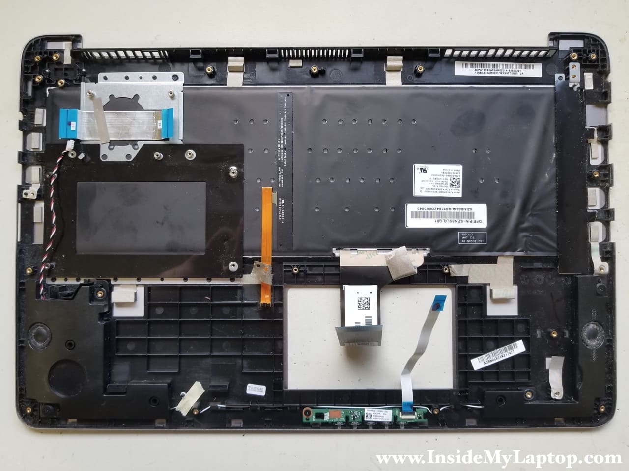
STEP 23.
Remove the trackpad.

STEP 24.
The LED board secured by one screw and can be easily removed too.

The keyboard is permanently attached to the palmrest assembly. It’s not easy to replace just the keyboard without replacing the entire top case.
Taking apart Asus K501U display panel
STEP 25.
Slide the hinge cover to the shown direction. This can be done only after the display panel separated from the palmrest assembly.

STEP 26.
Remove the hinge cover.
Remove two screws securing the front bezel to the display back cover.

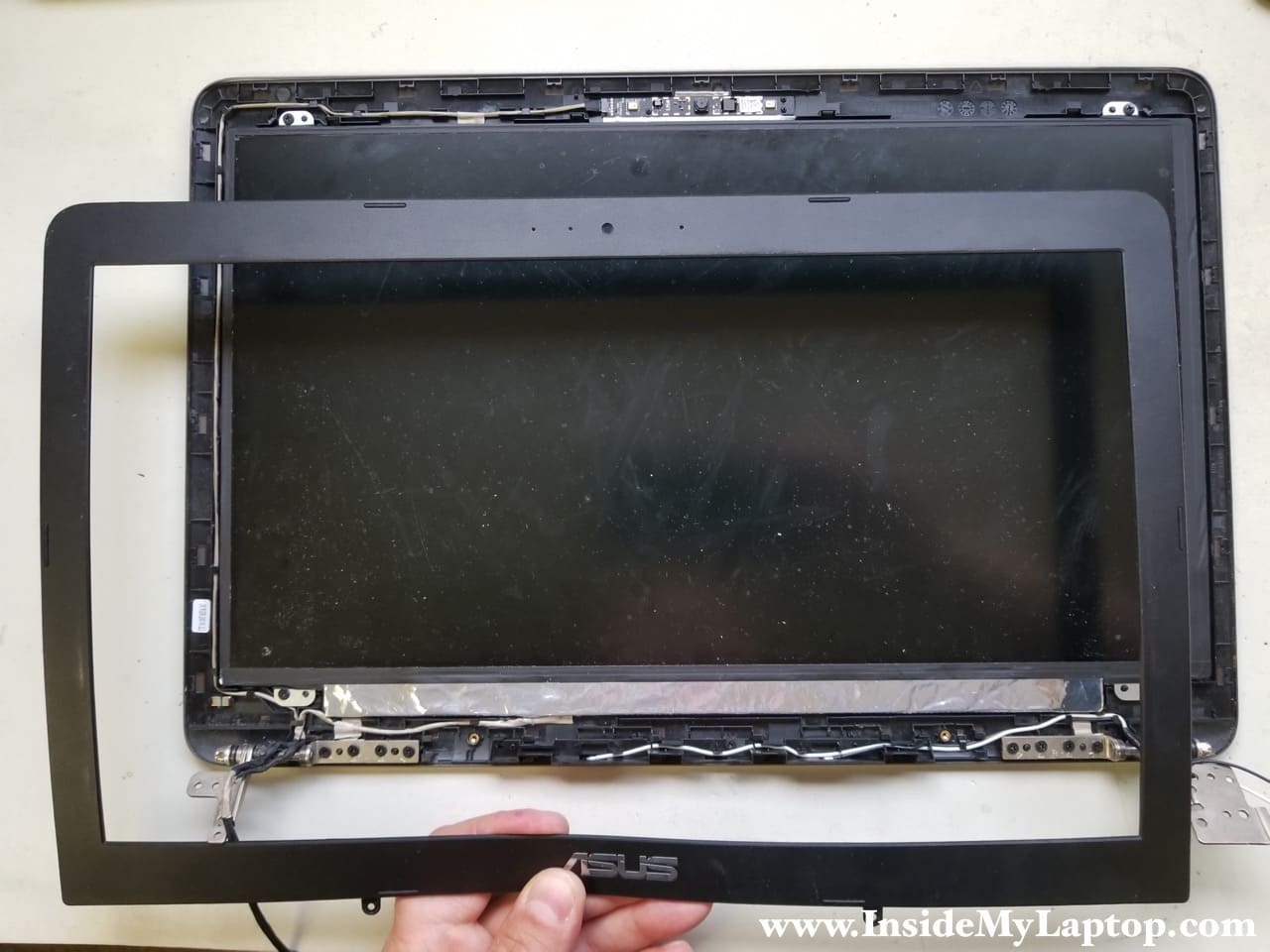
STEP 27.
Start separating the bezel from the back cover.

STEP 28.
Remove the display front bezel.
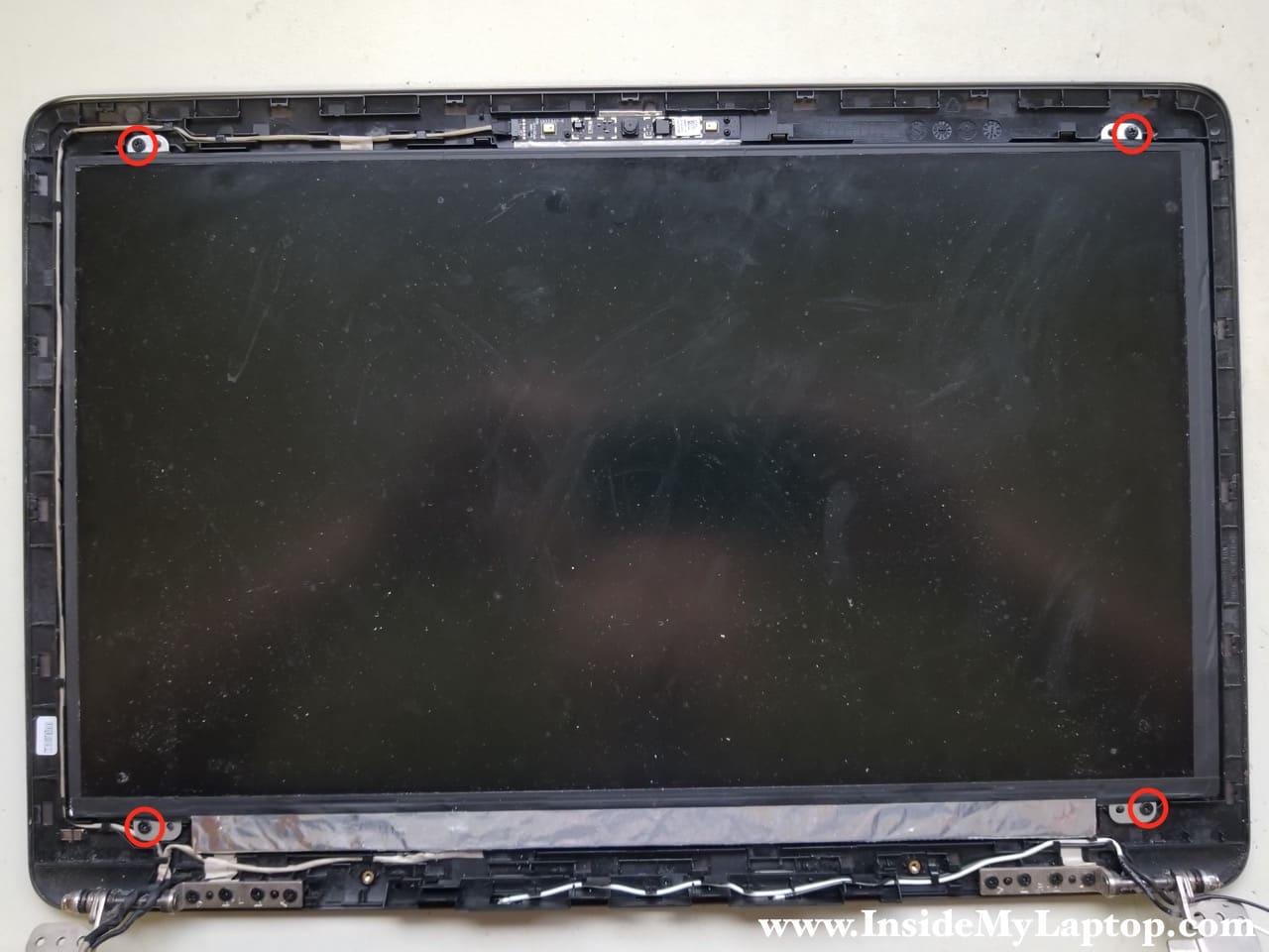
STEP 29.
Remove four screws securing the LCD screen to the back cover.
STEP 30.
Separate the LCD screen from the back cover to access the video cable connector on the back of the screen.

STEP 31.
Unplug the video cable from the screen.

You can find a new replacement LCD screen using the part number printed on the back of the original screen.
The screen model N156HGE-EAB.

Tina
I have a problem with charging battery. The laptop charges intermittently. To make it charge I have to move the adapter plug a little bit. After that it starts charging again but after a while stops again until I move the plug. How can I fix it?
IML Tech
Tina, it’s either bad AC adapter or failing DC jack (shown in the step 19). You can try another AC adapter. If the problem is still there, this is DC jack problem. To fix it, it’s necessary to remove the motherboard and replace the DC jack which is soldered to the motherboard. This should be done by a professional repair shop.
Again, check your power supply first.
RODRIGO RODRIGUES DA SILVA
What’s is the model for the flat cable video?
IML Tech
Search on eBay for “K501 cable” and you’ll find one.
I think the LVDS cable part number is 14005-01610600 or 14005-01611100.
marco
Some of my keys stopped working , how can I disconnect the keyboard ?
IML Tech
marco, in order to disconnect the keyboard it’s necessary to remove the laptop base cover (steps 1 and 2) and disconnect the keyboard cable from the motherboard (step 18). In the step 18 you can see the keyboard cable color-coded in yellow.
marco
Thank you!
marco
whats the cable in orange from step 18?
IML Tech
Just fixed it. The cable in orange is the keyboard backlight cable.
Hamza
I want to buy the right fan but i did not find it can you please help me and show me from where can i get one?
IML Tech
Did you look at the eBay links in the guide?
Daniel
The right hinge on my broke. Do you know if by merely opening it up that the hinge can be replaced without significant difficulty? Or would it require replacing the entire displace/screen panel?
Brendan
Hi, very informative page many thanks for putting it up. I have the exact same laptop (i5 8gB RAM) as above with a blown motherboard from an incorrectly plugged in charger. I had it in for repair but they said was not repairable. I’m wondering if I was to replace the entire motherboard is it possible to also upgrade to an i7 model?
Archie Gallacher
Hi from the UK.
Can you tell me please, does the Asus k501u have a cmos battery installed and if so, where would I find it?
Thanks in advance,
Archie.
IML Tech
I don’t think this model has a CMOS battery.