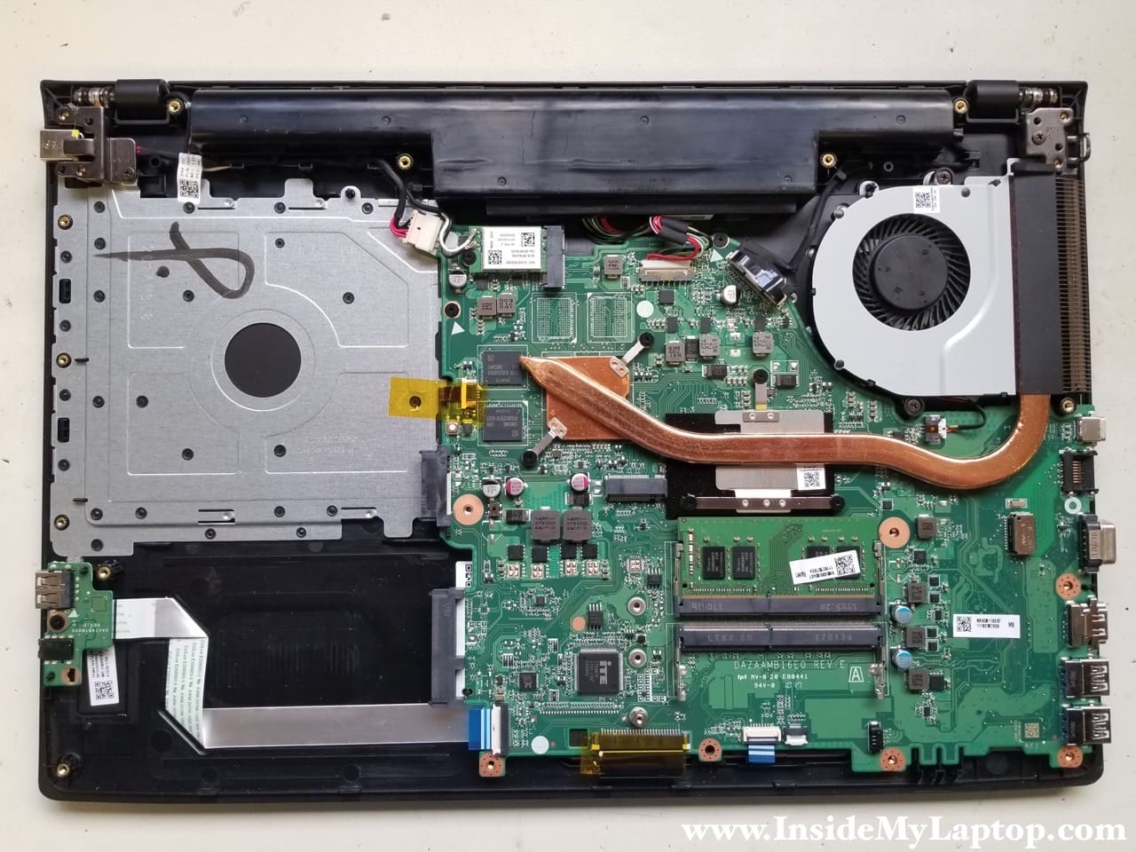
In this guide I will show how to disassemble an Acer Aspire E5-575 series laptop. Model number N16Q2.
This is an Aspire E5-575G-57D4 configuration (7th generation Intel Core i5) manufactured in 2017.
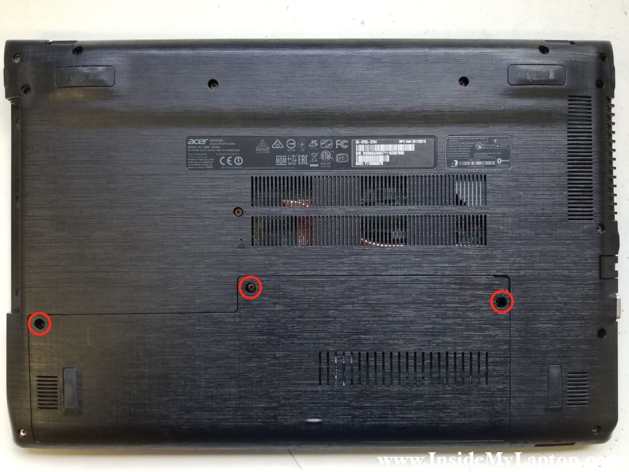
STEP 1.
Remove three screws from the service cover. Remove the cover.
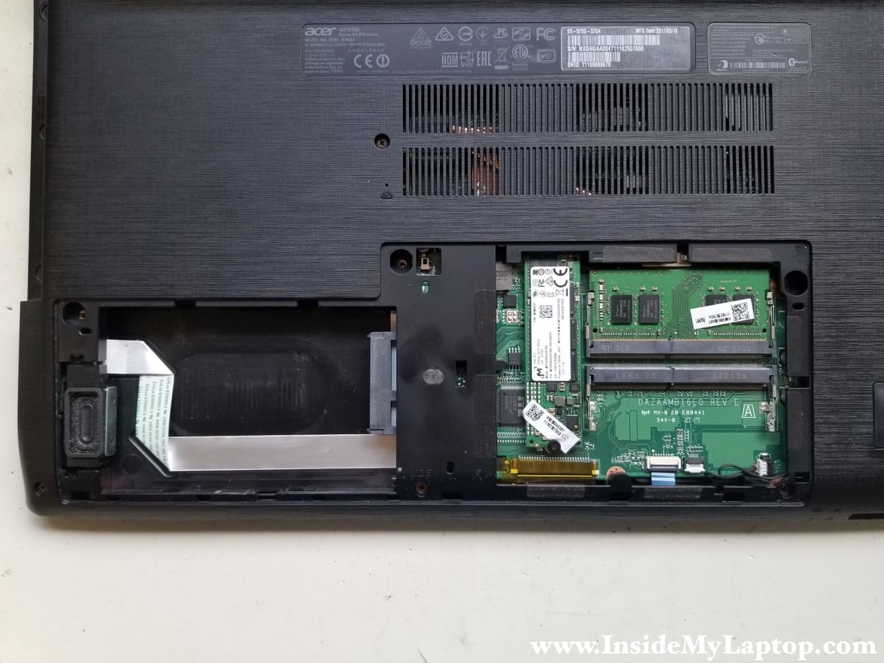
STEP 2.
Under the cover you can access the hard drive bay, SSD and both memory slots.
Acer Aspire E5-575 has support for a regular 2.5″ SATA hard drive (missing in my case) and M.2 SSD.
This laptop can take up to 32GB (2x16GB) DDR4 2400/2666/3200 SODIMM RAM modules.
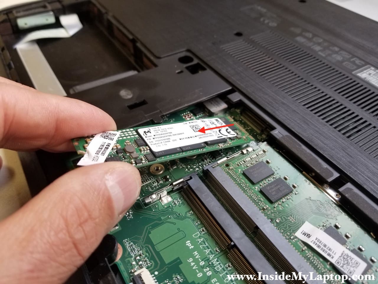
STEP 3.
Remove one screw securing the SSD and pull it out of the socket.
This is m.2 SATA III solid state drive.
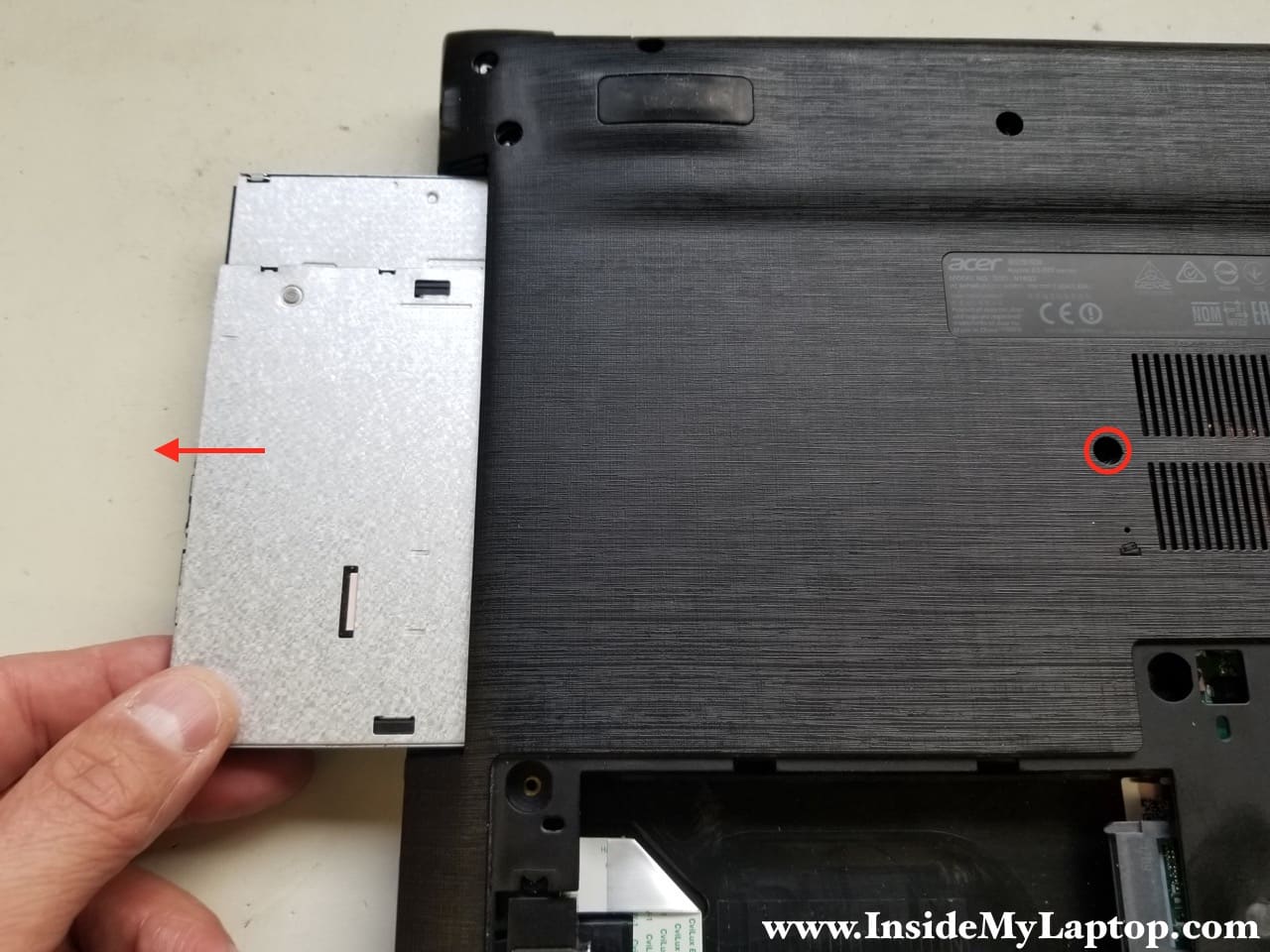
STEP 4.
Remove one screw securing the optical drive and pull it out. In my laptop the front bezel is missing so it looks different than yours.
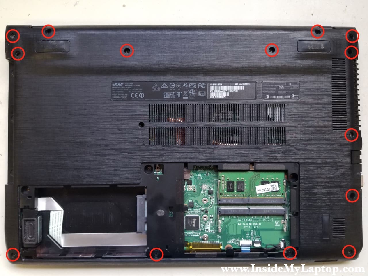
STEP 5.
Remove all screws from the bottom case.
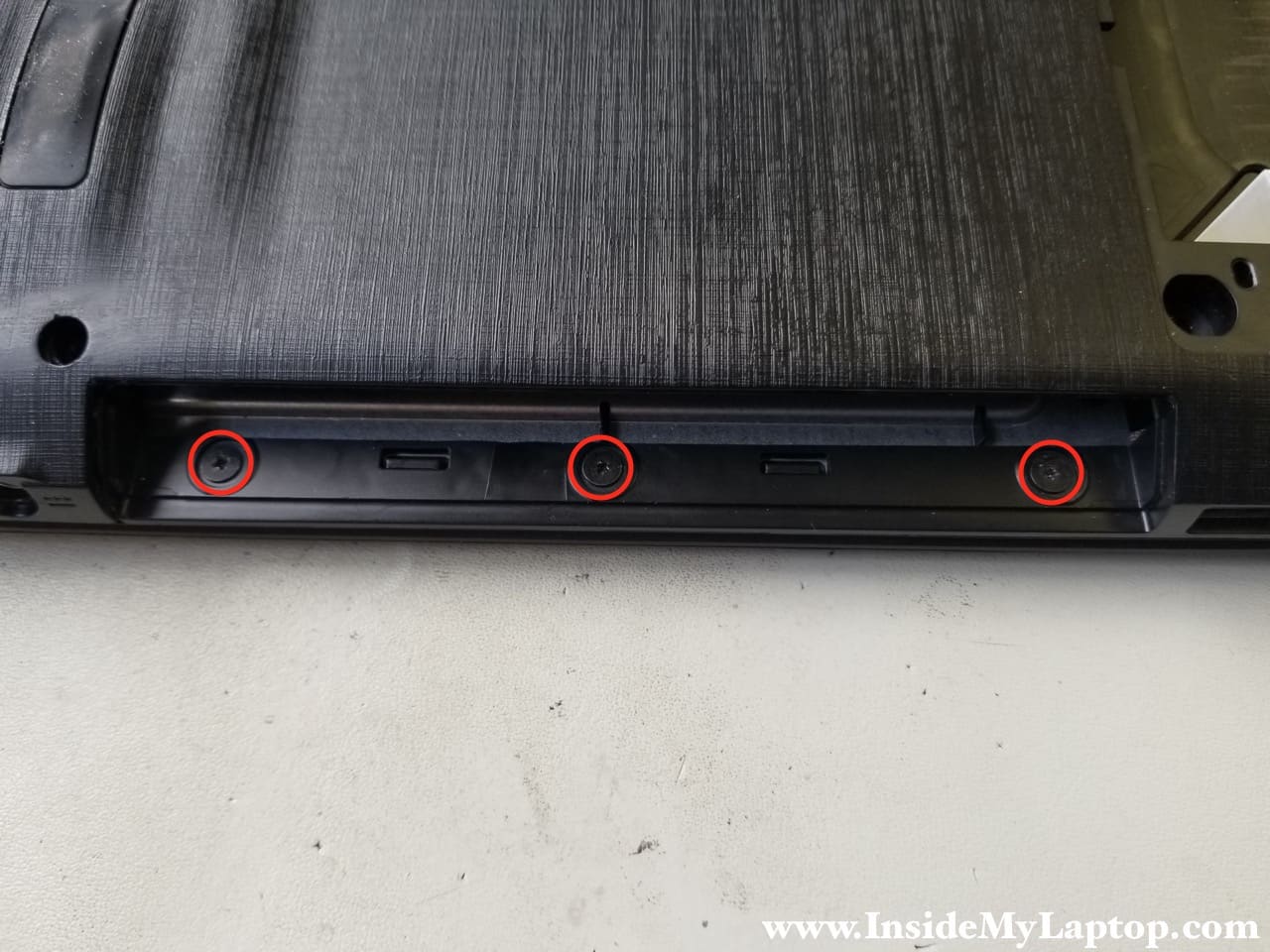
STEP 6.
Remove three more screws located in the optical drive bay.
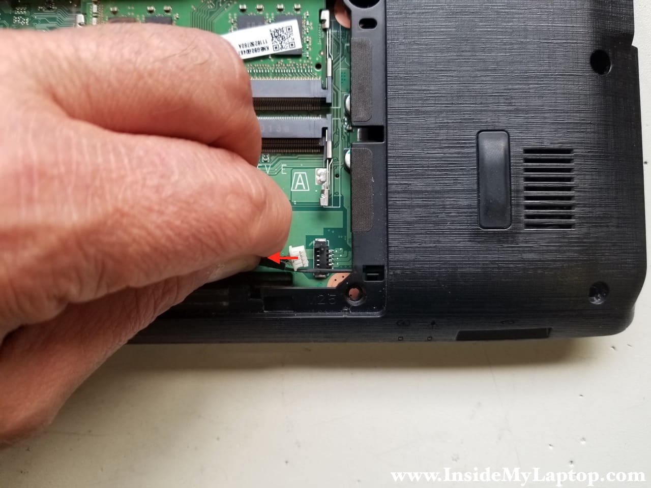
STEP 7.
Don’t forget to disconnect speakers cable. Both speakers are mounted to the bottom case.
STEP 8.
Start separating the bottom case from the side with the optical drive bay. On the other side the case has cut-outs for the motherboard connection ports.
If you start removing it on the other side, the connection ports will not allow you to lift up the bottom case.

STEP 9.
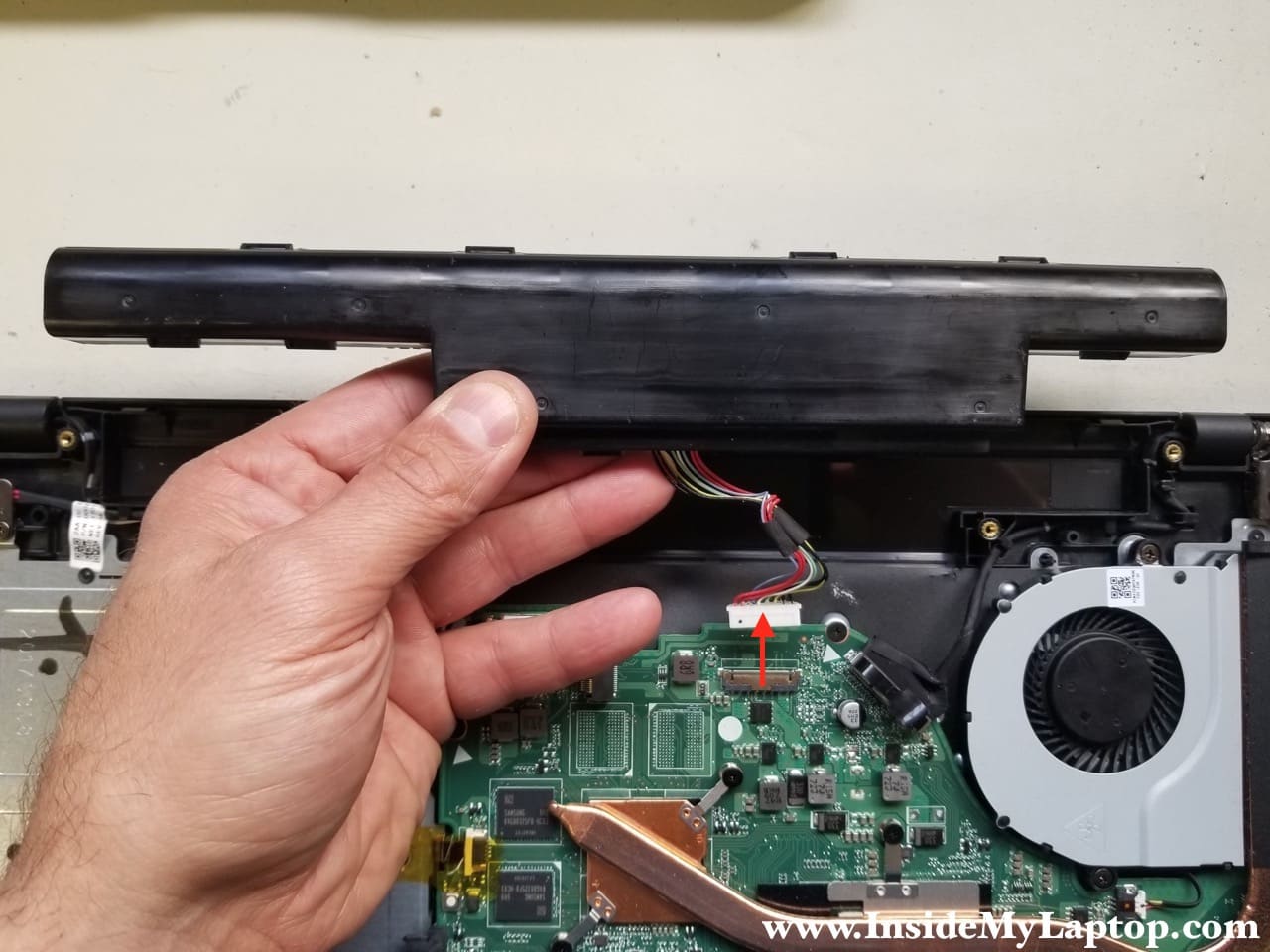
The battery is not secured and can be easily removed.
Lift up the battery and disconnect it from the motherboard.
STEP 10.
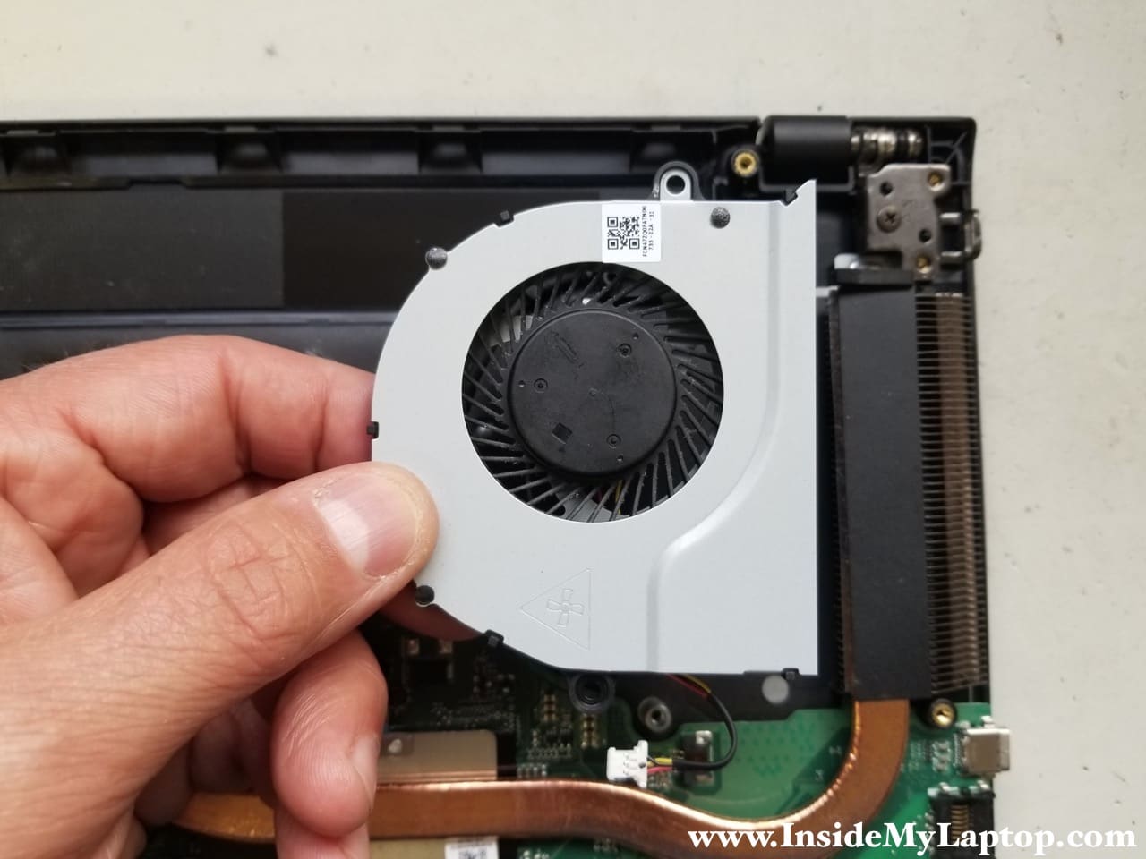
Remove two screws securing the cooling fan and disconnect the cable from the motherboard.
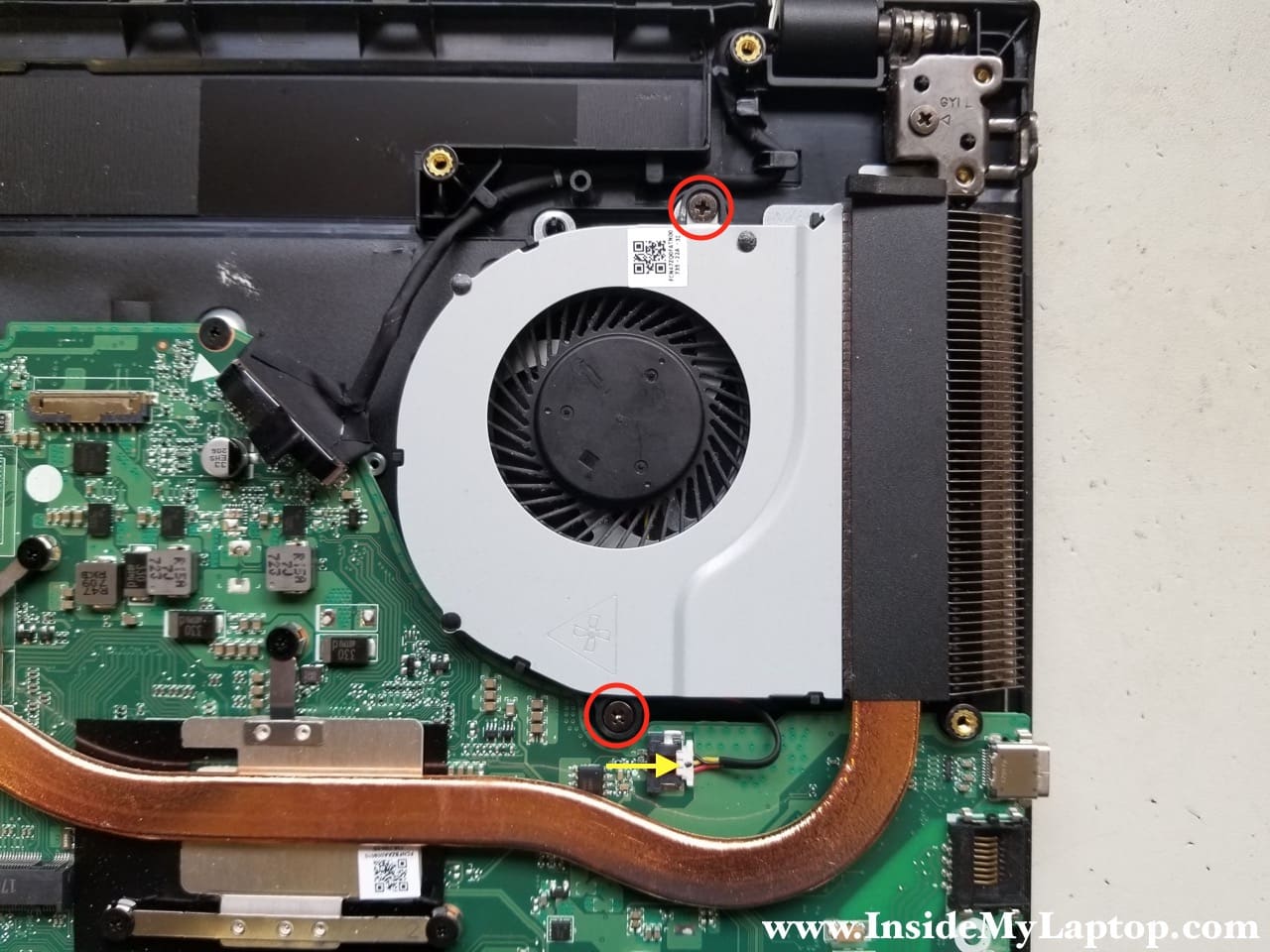
Remove the fan.
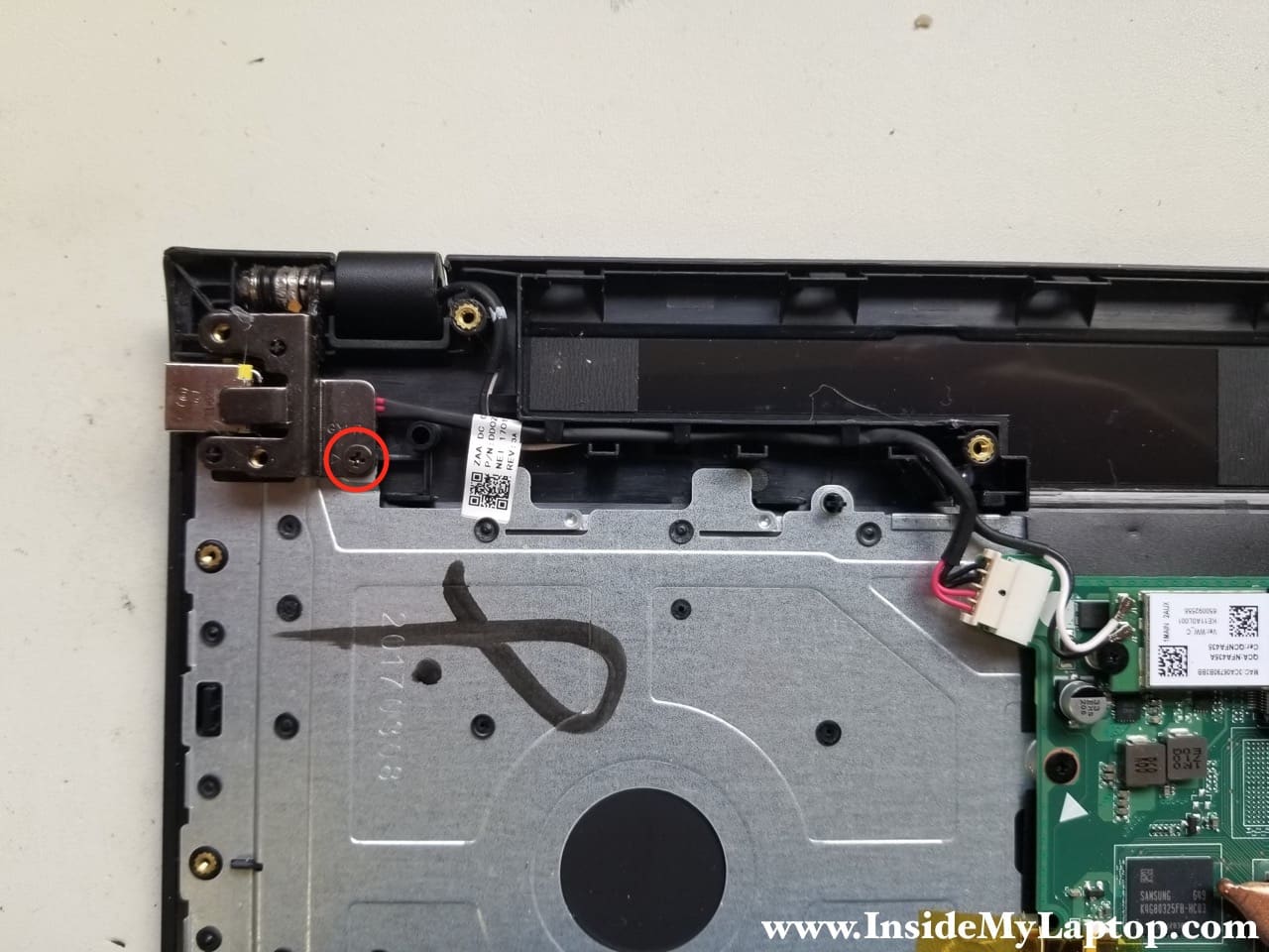
STEP 11.
The DC power jack is mounted under the right hinge.
Remove one screw securing the hinge.
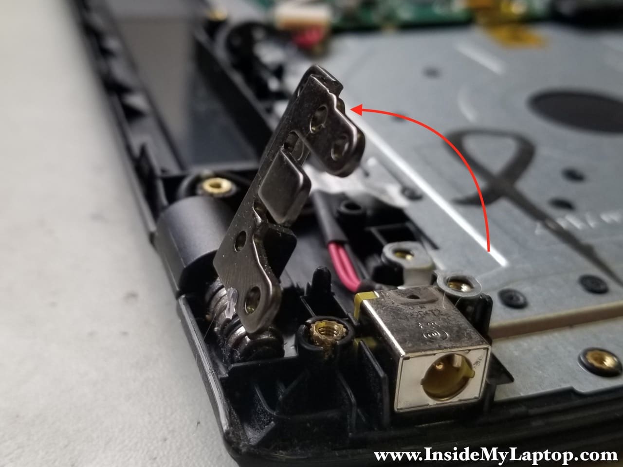
STEP 12.
Lift up the right side of the hinge so it opens up at a 60 degree angle.
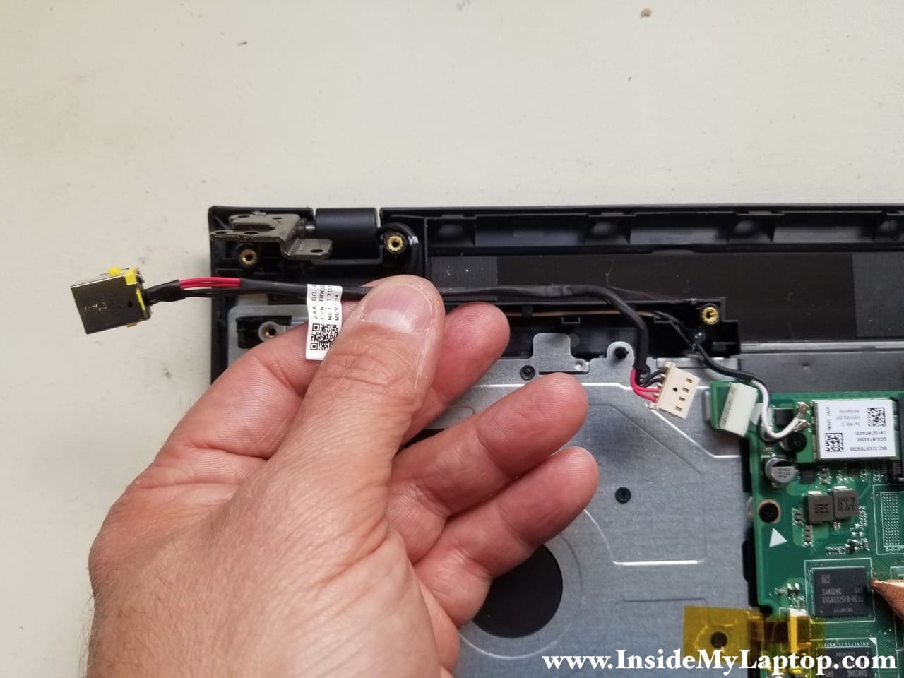
STEP 13.
Disconnect the DC power jack cable from the motherboard and remove it.
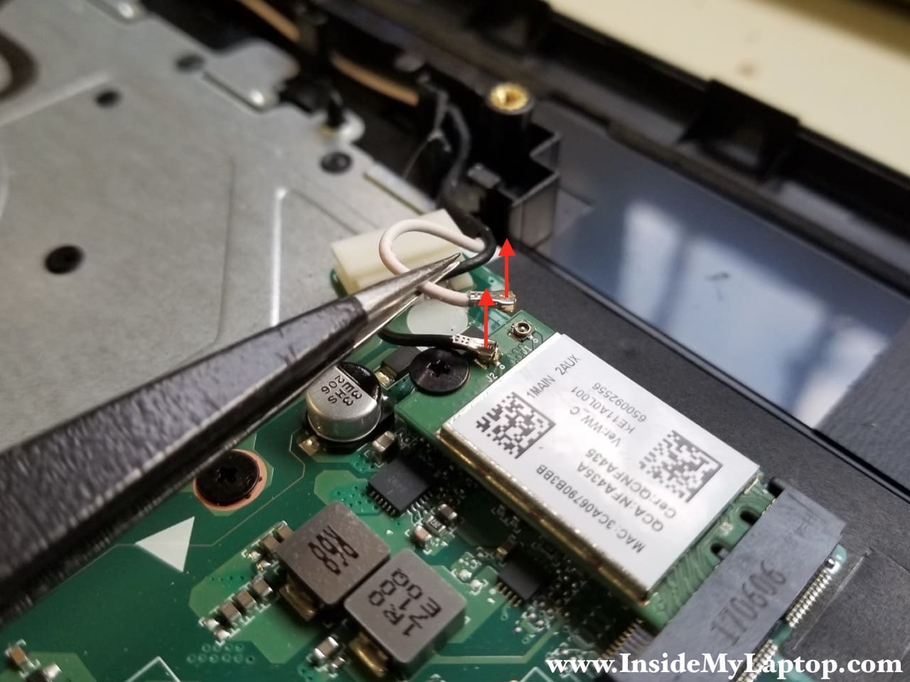
STEP 14.
Disconnect both Wi-Fi antenna cables from the wireless card. You can leave the card connected to the motherboard.
STEP 15.
Remove two screws.
Disconnect the following cables:
- Keyboard backlight cable
- USB/Audio board cable
- Keyboard data cable
- Touchpad cable
- Display video cable
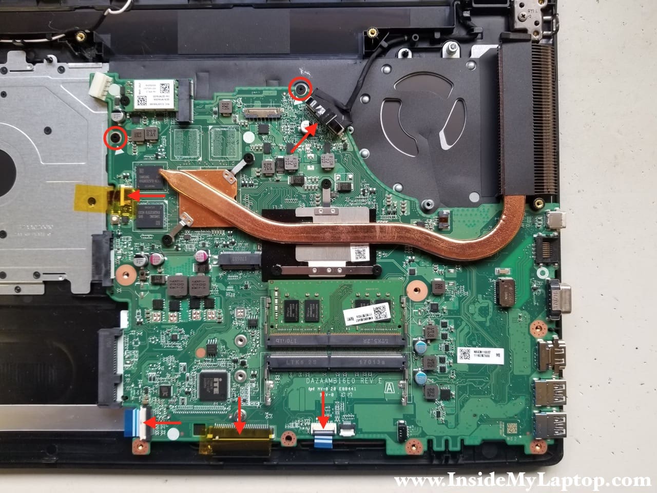
Here’s how to disconnect the display video cable. Simply pull it up.

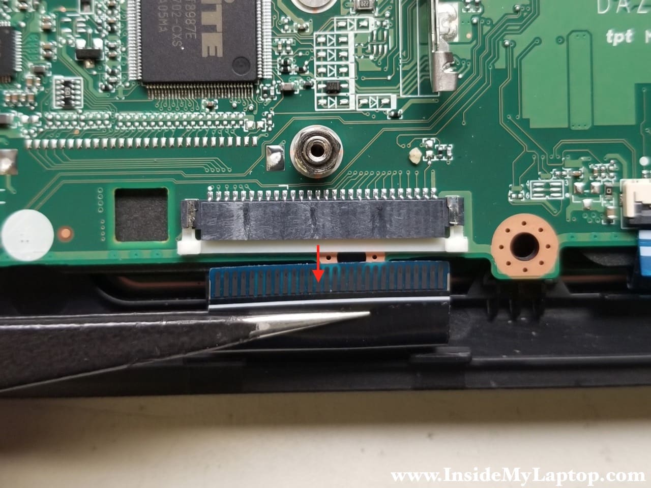
Here’s another type of connector you will see on the motherboard. In this case you unlock the connector by lifting up the locking tab (red arrow).

In order to unlock the keyboard cable connector you will have to move the locking tab about 2 millimeters to the direction shown on the picture.
Do not apply any force. The locking tab must remain connected to the base.

When the connector is unlocked, you can pull the cable out.
STEP 16.
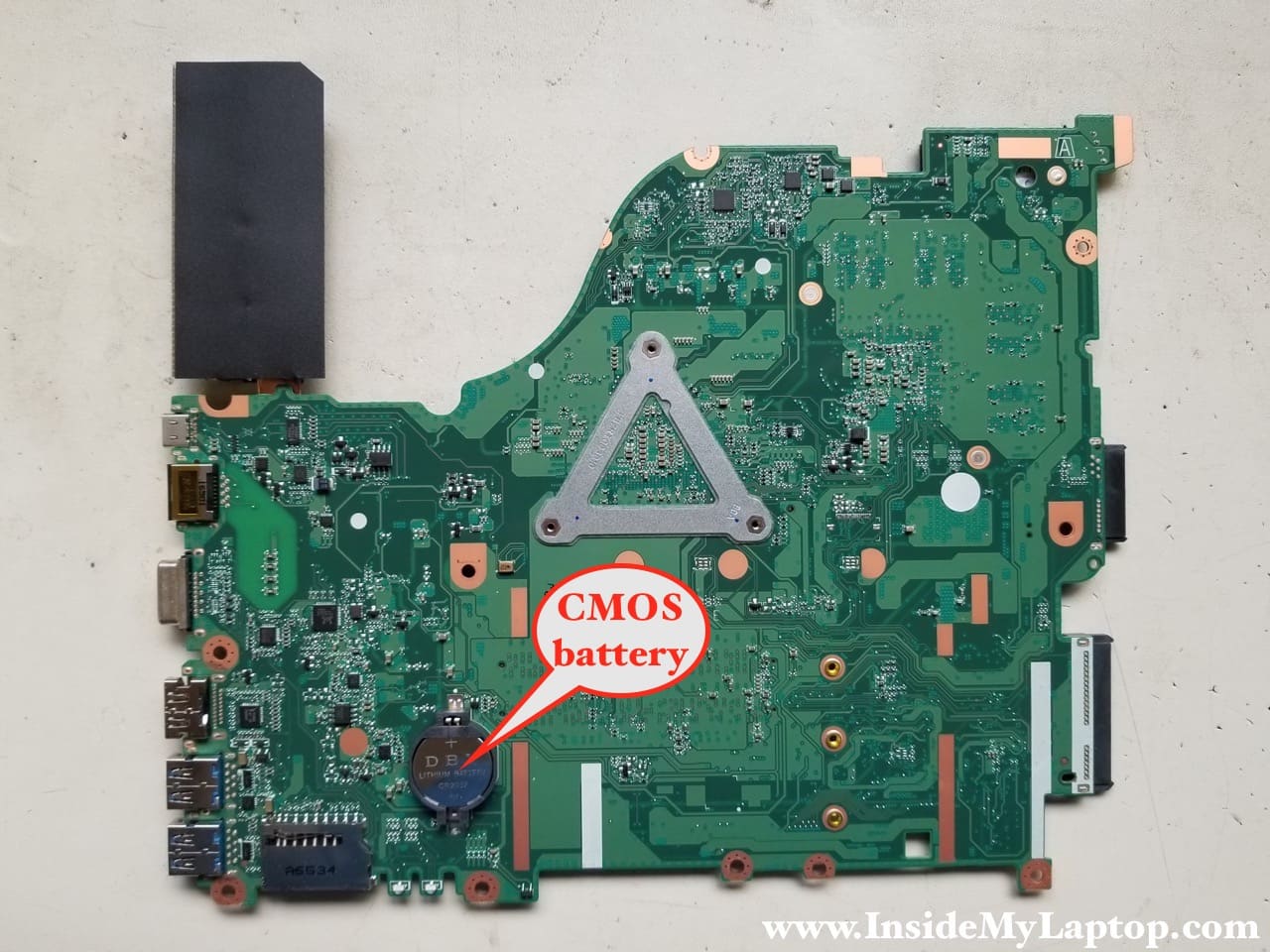
Remove the motherboard from the top case.

You can access the CMOS battery on the other side.
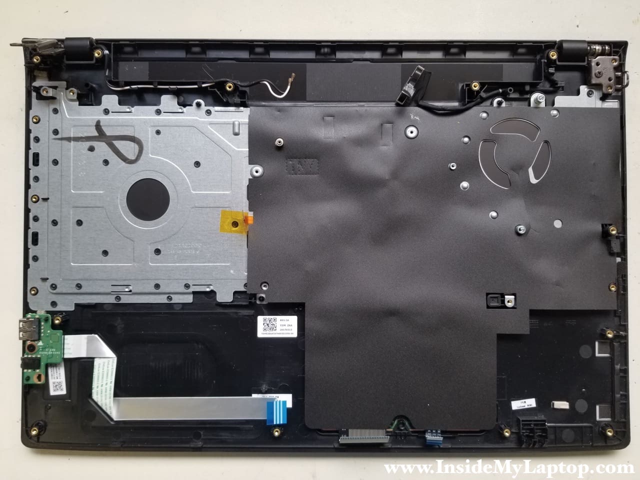
The touchpad assembly located under the black mylar sheet.

In Acer Aspire E5-575 series laptops the keyboard is permanently attached to the top case.
There are multiple plastic rivets securing the keyboard to the frame.
It’s possible to replace just the keyboard itself without replacing the top case. You will have to remove all the rivets and find a way to secure the metal cover back to the top case after installing a new keyboard.
If the keyboard failed, I would recommend replacing the entire top case assembly.
The screen removal procedure will be very similar for most Acer laptops.
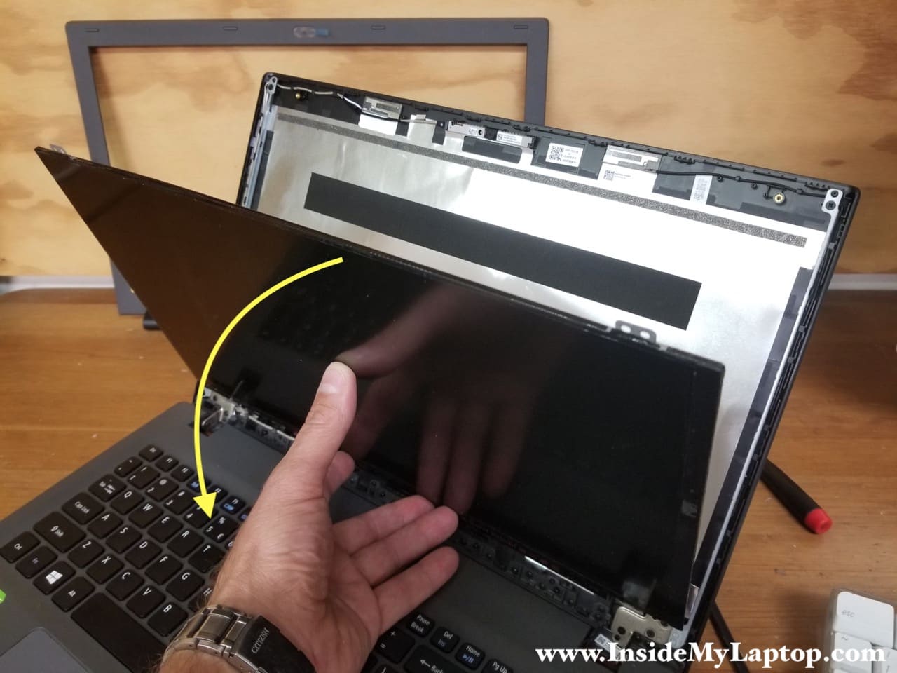
In the next guide I’ll explain how to take apart the display panel and replace LCD screen.
Corrina
thanks, this is perfect for my E5-575G! But I was confused by the title saying 571 series, I almost didn’t click on it.
IML Tech
My bad. Fixed. It’s Acer Aspire E5-575.
Giovanni
Could you show us how to replace touchpad too?
aedyall
Fantastic resource, ThankYouSoMuch!
Ahmad sharif
Thanks so much this helped me but I need how to remove WiFi card and add pci e for egpu for gaming please help
IML Tech
You cannot do that.
David Hodges
Thank you for the great step-by-step pictures and text. I have the same model. Is acer always so difficult to get specifications. I bought this laptop from someone who bought it from someone. There was no microsoft sticker on it. Is it windows 7, 8, or 10?
IML Tech
I think the default is 10. Try installing Windows 10 Home. In most cases it will activate itself with a digital license.