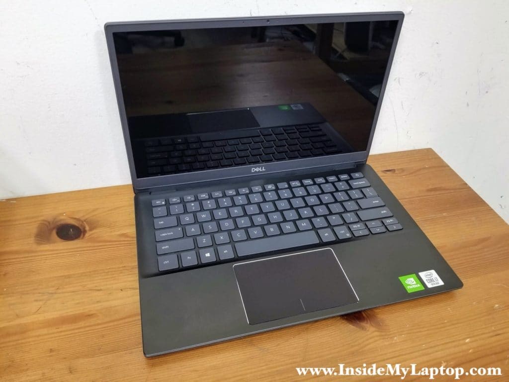
In this guide I will walk you through a Dell Vostro 5391 laptop (model P114G) disassembly. At the time of writing this disassembly tutorial, Dell Vostro 5391 is one of the latest models featuring Intel Core i7 10th Generation processor.
Also, you can use this guide for taking apart a Dell Inspiron 5391 laptop, which is very similar. I’ll make a dedicated guide for that model when I have a chance.
Here are some pros and cons of Dell Vostro 5391 laptop design:
– The power button and DC jack are removable and replaceable.
– The cooling fan is not attached to the heatsink and can be replaced separately.
– The memory is non-removable. It’s either 8GB or 16GB built-in into the motherboard.
– The keyboard is permanently attached to the top case.
For this disassembly you need only three basic tools: Phillips screwdriver #0 or #1, tweezers, case opener tool.
Removing the battery
STEP 1.
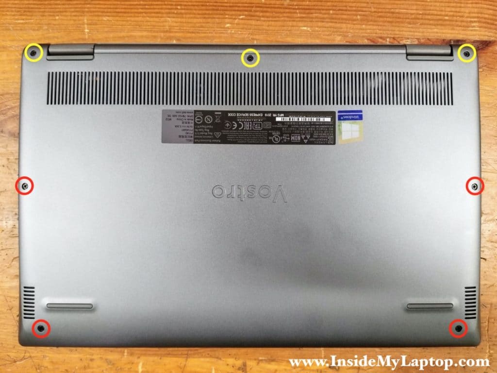
Loosen three captive screws (yellow) and remove four regular screws (red) securing the base cover.
STEP 2.
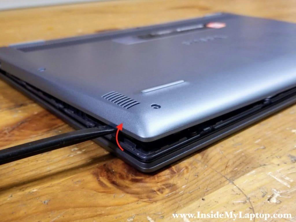
Using a case opener tool pry up the base cover. Continue removing the cover with your hands. You have to apply some reasonable force in order to separate two parts from each other.
STEP 3.
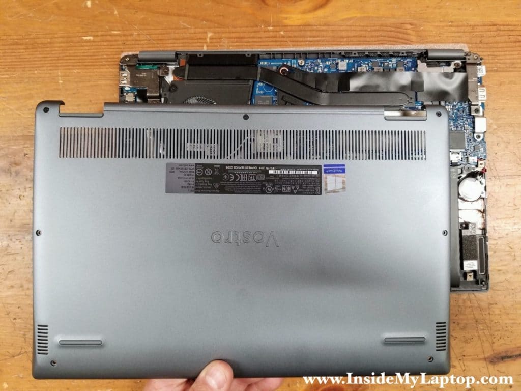
Remove the base cover.
STEP 4.
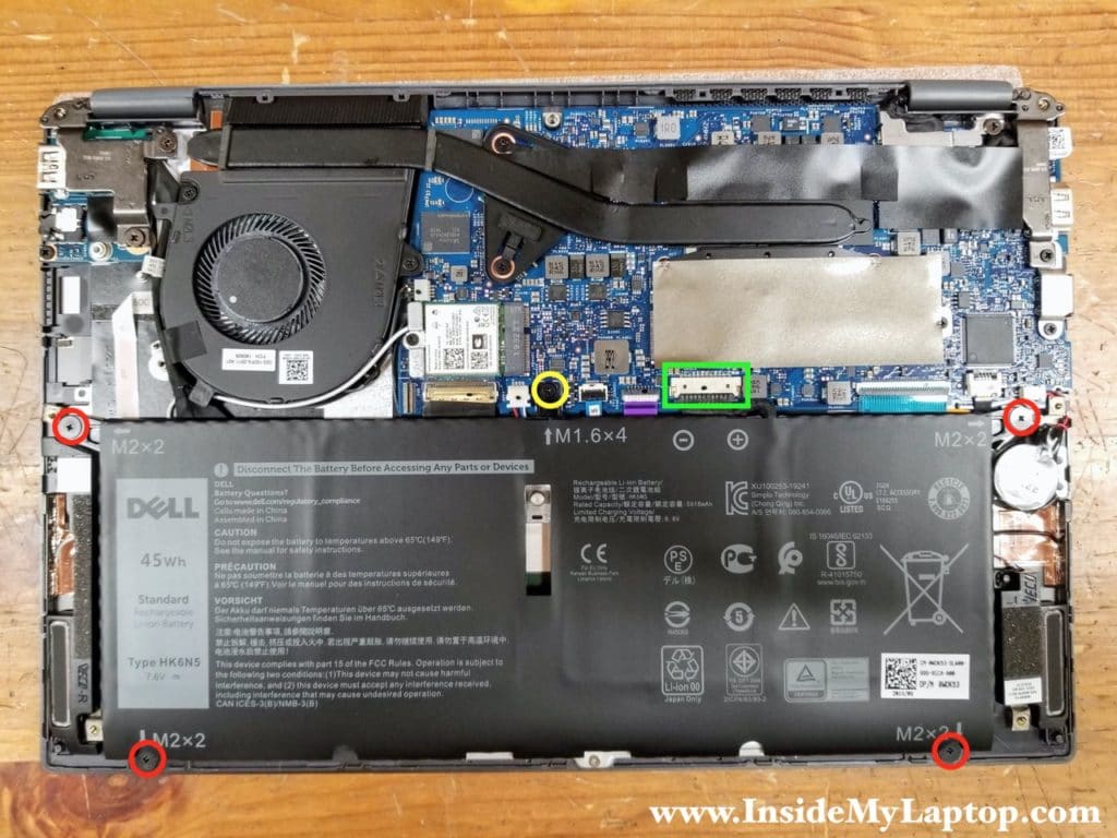
Remove four regular screws and loosen one captive screw securing the battery.
STEP 5.
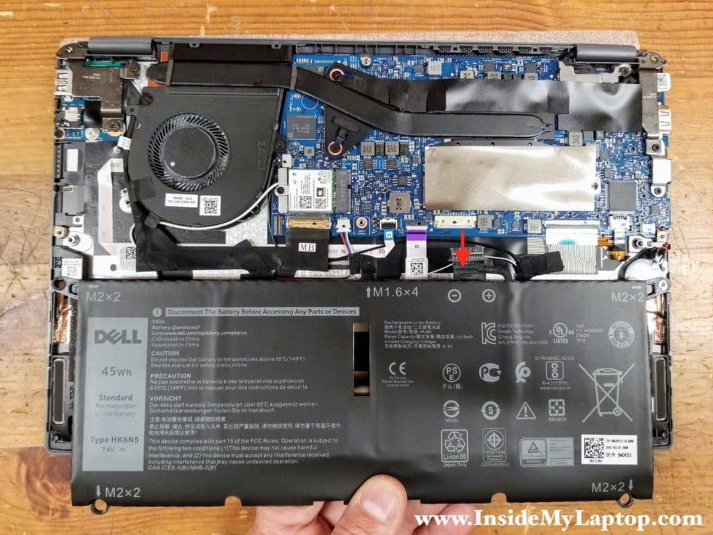
Lift up the battery and disconnect the cable from the motherboard.
Dell Vostro 5391 battery type: HK6N5.
Dell part number: 0WDK63.
Removing the SSD, fan and DC jack
STEP 6.
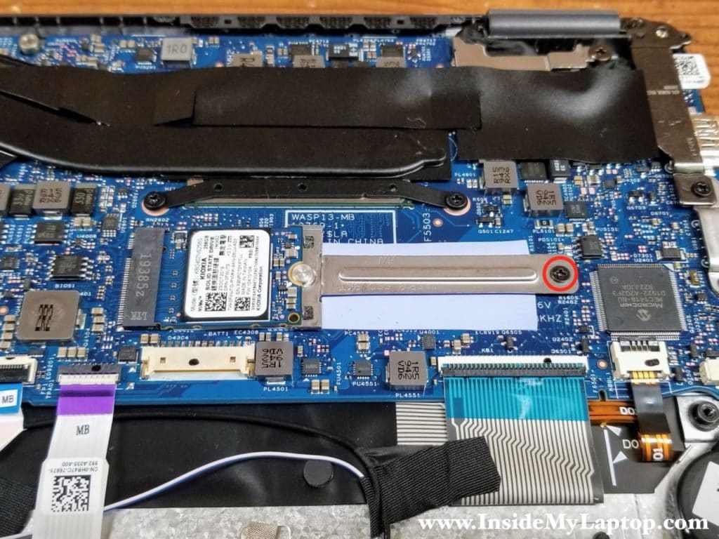
The solid state drive hidden under the gray self-adhesive tape. Peel off the tape to expose the solid state drive.
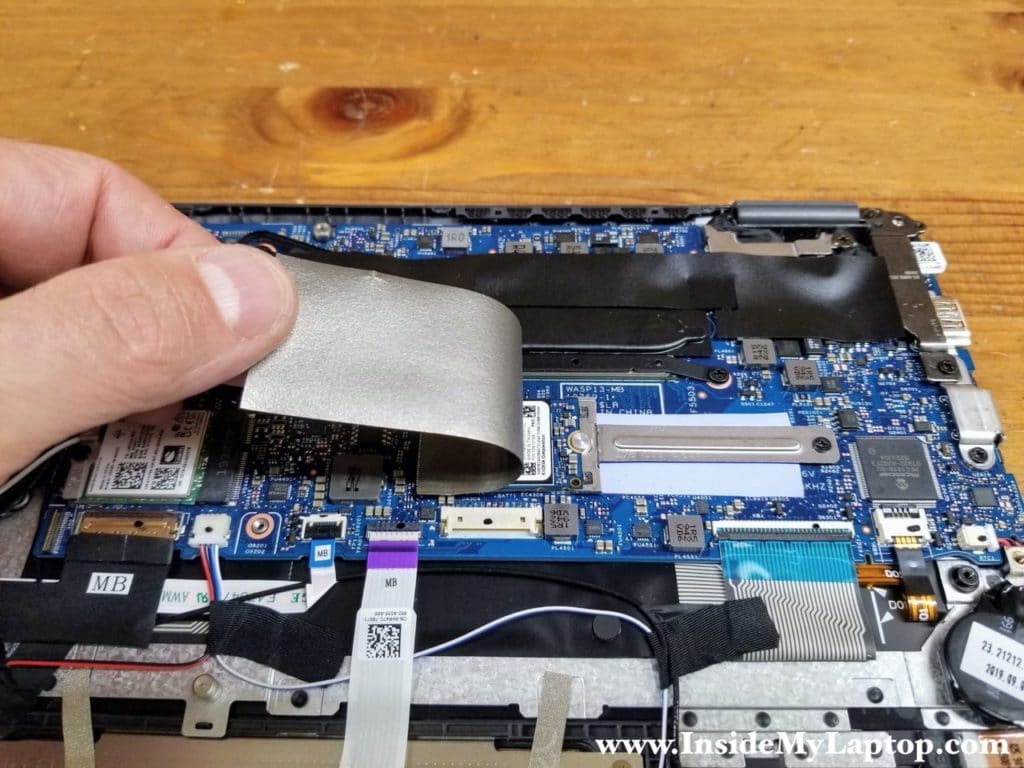
In this particular Dell Vostro 5391 laptop came with a short (type 2230) SSD installed which requires a mounting bracket. This is a 256GB PCIe NVMe M.2 SSD.
You can replace or upgrade it with a regular size (type 2280) PCIe NVMe M.2 SSD.
STEP 7.
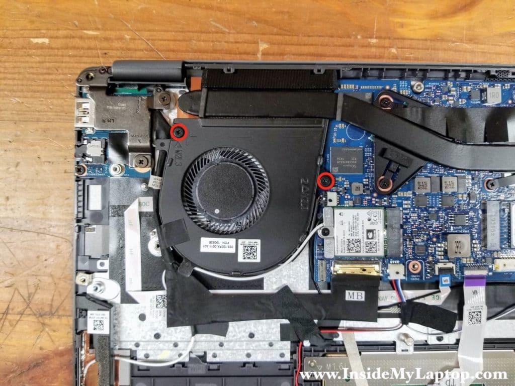
Remove two screws from the cooling fan.
STEP 8.
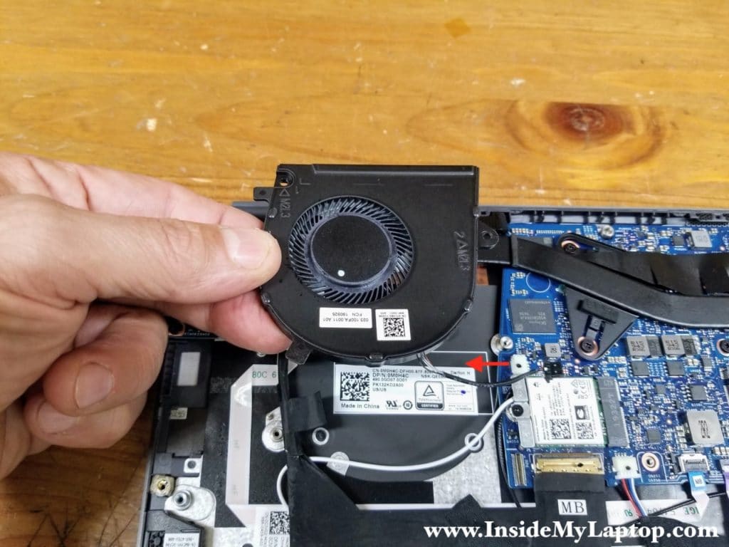
Lift up the fan and disconnect the cable from the motherboard. Remove the fan.
STEP 9.
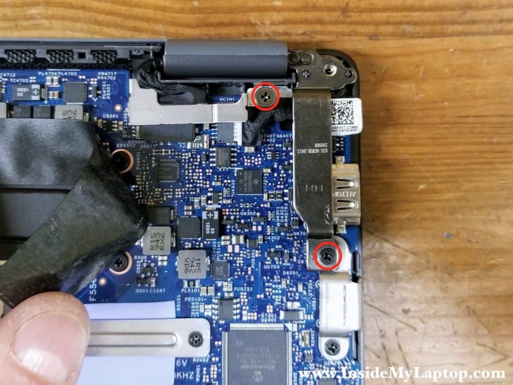
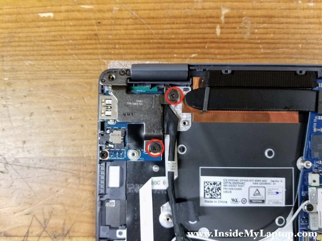
Remove one screw from the display cable bracket and remove one screw from the display hinge. The DC power jack is mounted under the hinge.
STEP 10.
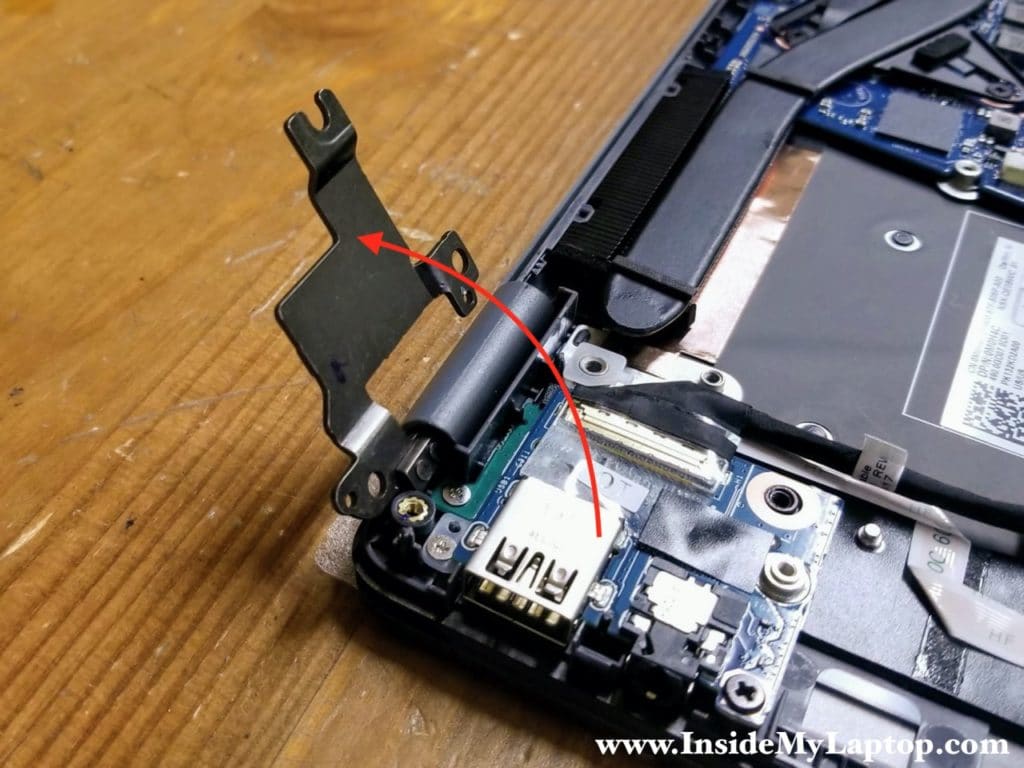
Remove the display cable bracket and lift up the hinge as it shown on the following picture.
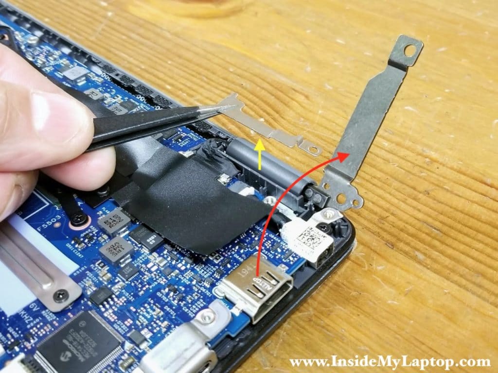
STEP 11.
Remove one screw securing the DC-IN power jack.
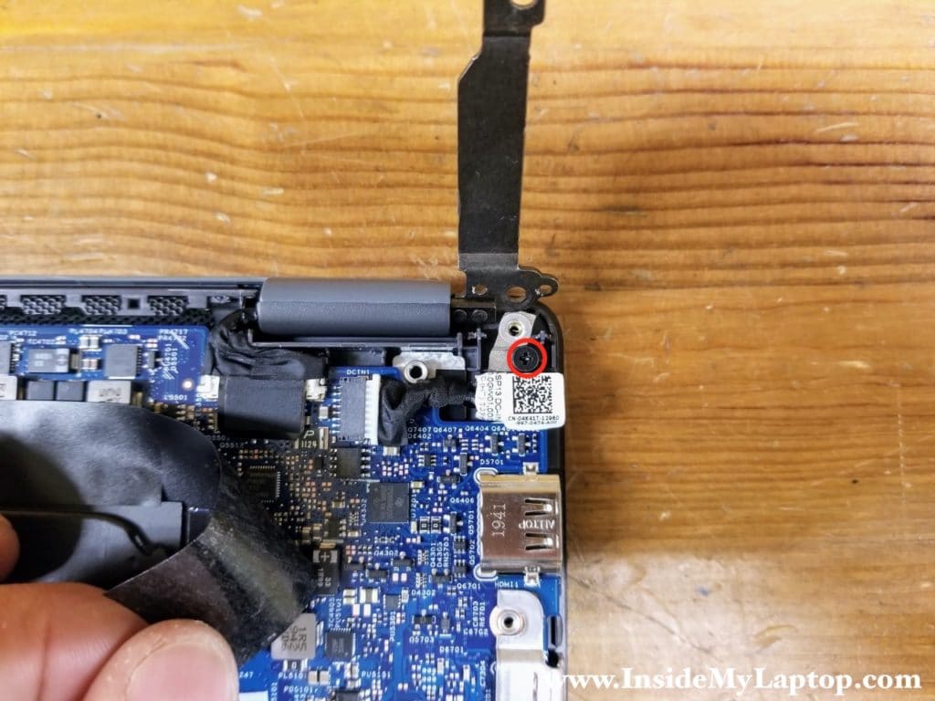
STEP 12.
Lift up the DC jack and disconnect it from the motherboard. Remove the DC jack.
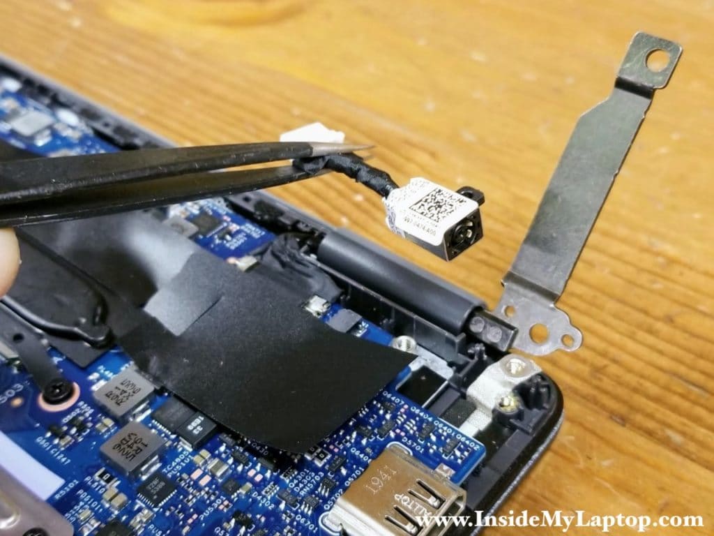
Removing the display panel
STEP 13.
Disconnect the display cable from the motherboard. There is a black tab on the top of the connector. Pull the tab up to unplug the cable. Disconnecting the display cable is necessary if you plan to remove the display or the motherboard.
WARNING: the display cable has a fragile connector. Make sure it’s aligned correctly when you connect it back to the motherboard.
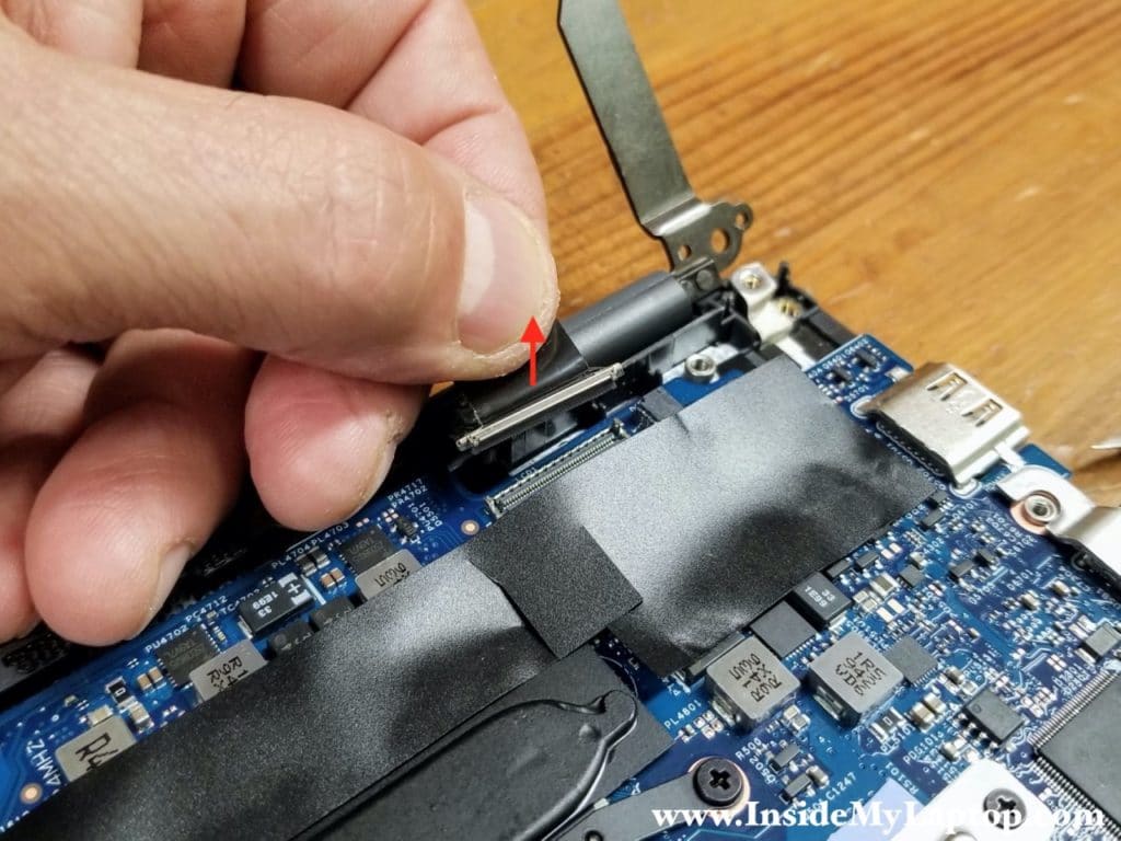
STEP 14.
Remove two screws from the display hinge on the other side.
STEP 15.
Lift up the display hinge.
STEP 16.
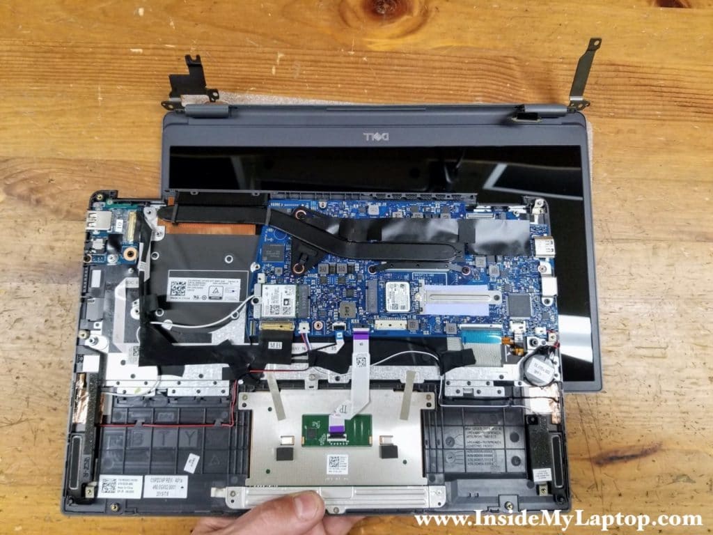
With the display cable disconnected and both hinges lifted up, you can separate the display panel from the top case assembly.
Removing the USB board and power button
STEP 17.
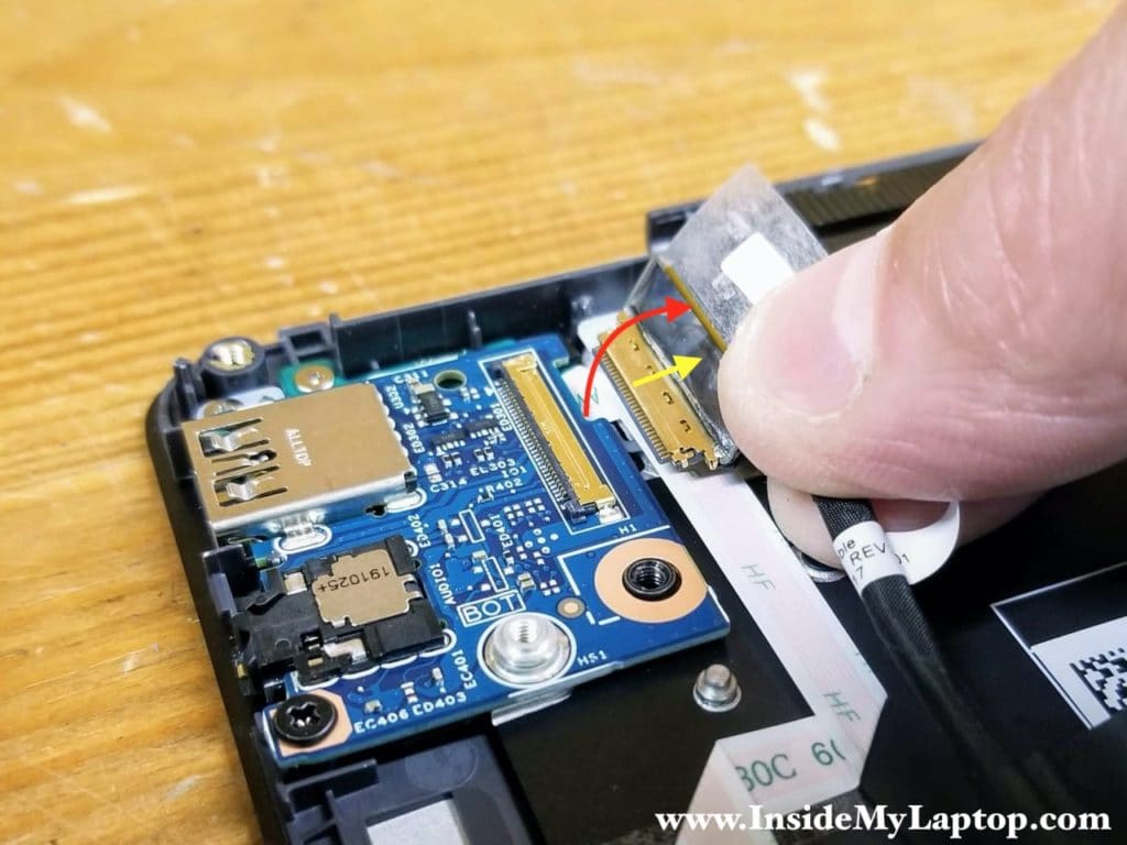
Remove two screws from the USB audio board and disconnect the I/O cable.
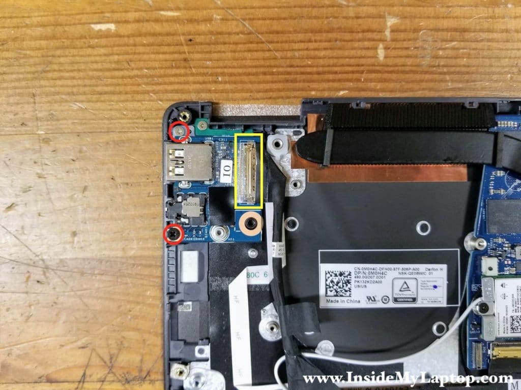
Here’s how to disconnect the I/O cable from the USB audio board.
Peel off clear tape securing the connection. Lift up the metal bracket to unlock the connector (red arrow). Pull the cable out (yellow arrow).
STEP 18.
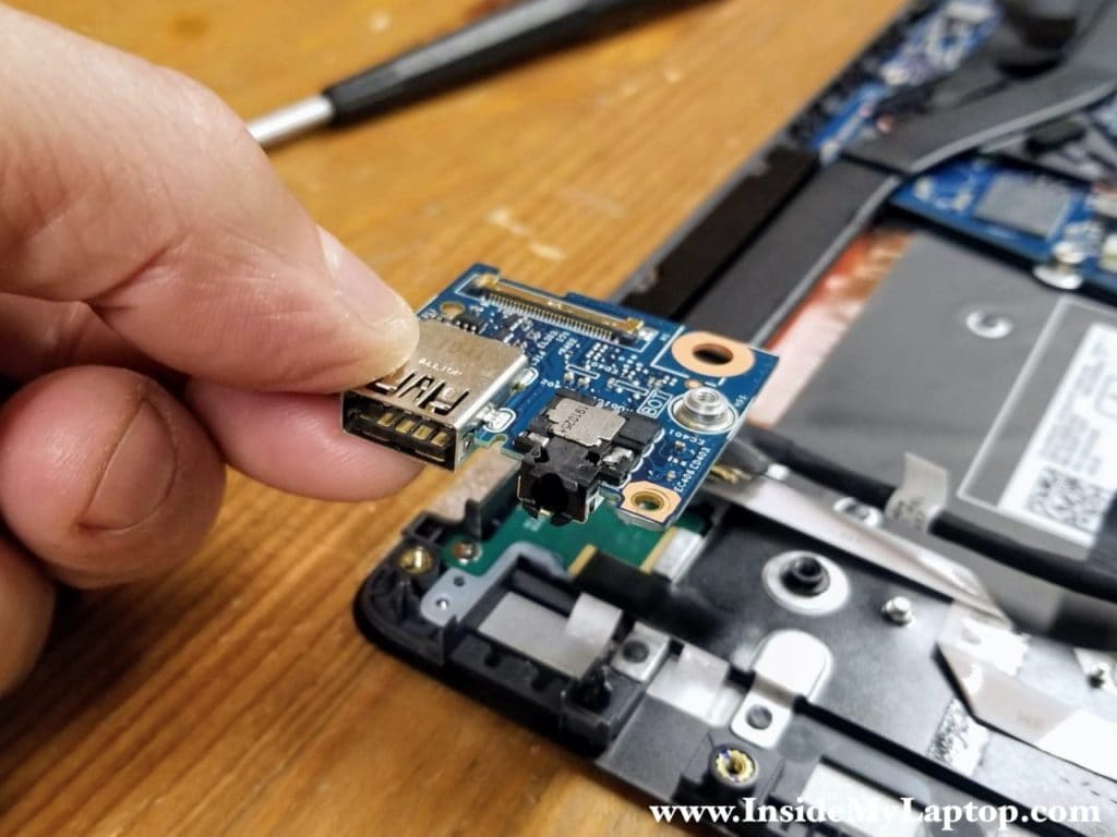
Lift up and remove the USB audio board.
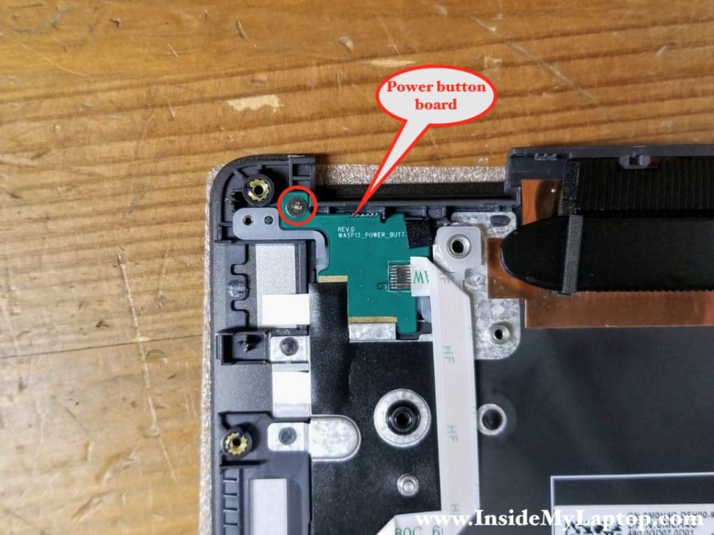
From outside it looks like the power button is a part of the keyboard but it’s not. The power button located on a separate board and can be easily removed and replaced. Simply remove one screw securing the power board and disconnect the cable from the motherboard.
Removing the motherboard
STEP 19.
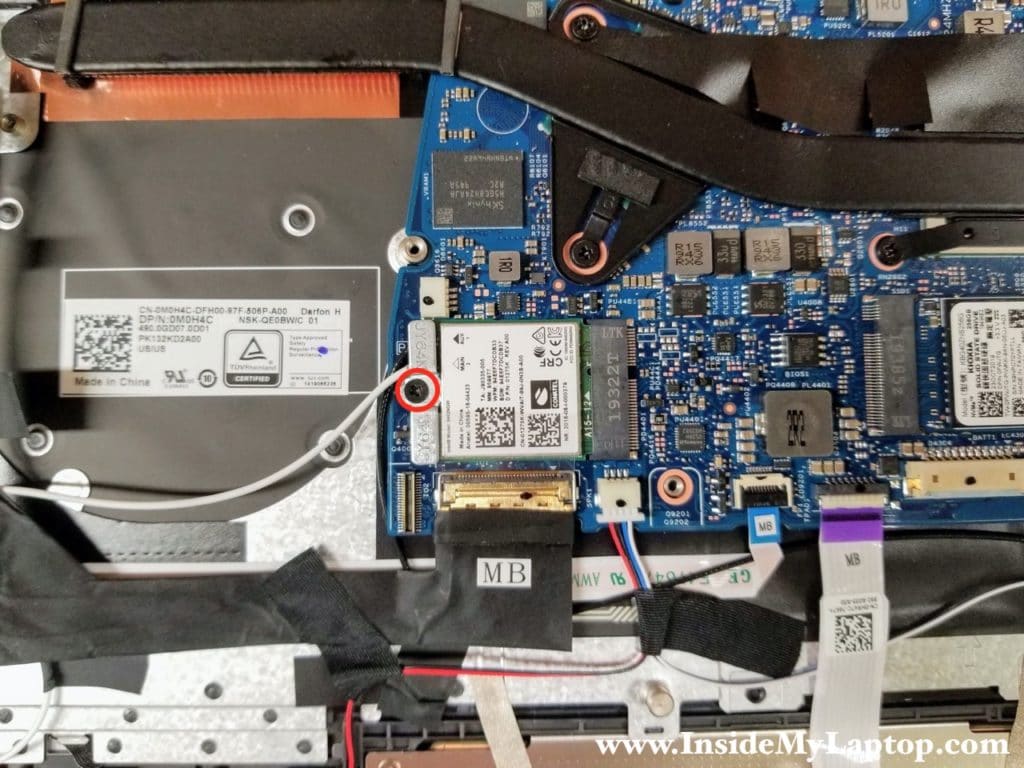
Remove one screw from the Wi-Fi card bracket.
STEP 20.
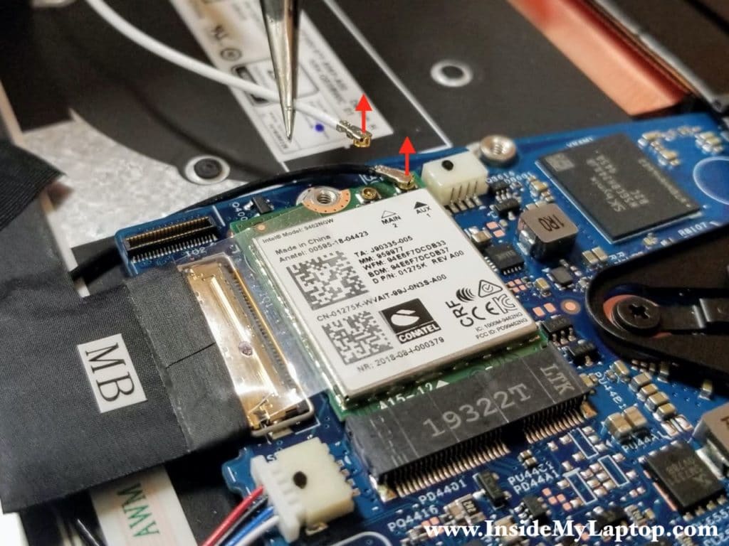
Disconnect both antenna cables from the Wi-Fi card. You can leave the Wi-Fi card attached to the motherboard and pull it out if necessary.
STEP 21.
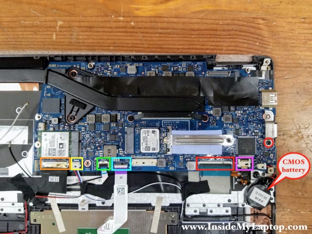
To remove the motherboard it’s necessary to remove one screw and disconnect the following color-coded cables:
– USB audio board cable (orange).
– Speaker cable (yellow).
– Power button board cable (green).
– Trackpad cable (blue).
– Keyboard cable (red).
– Keyboard backlight cable (pink).
You can disconnect the CMOS battery if necessary or leave it connected to preserve the BIOS settings. After that you can separate the motherboard from the top case and remove it.
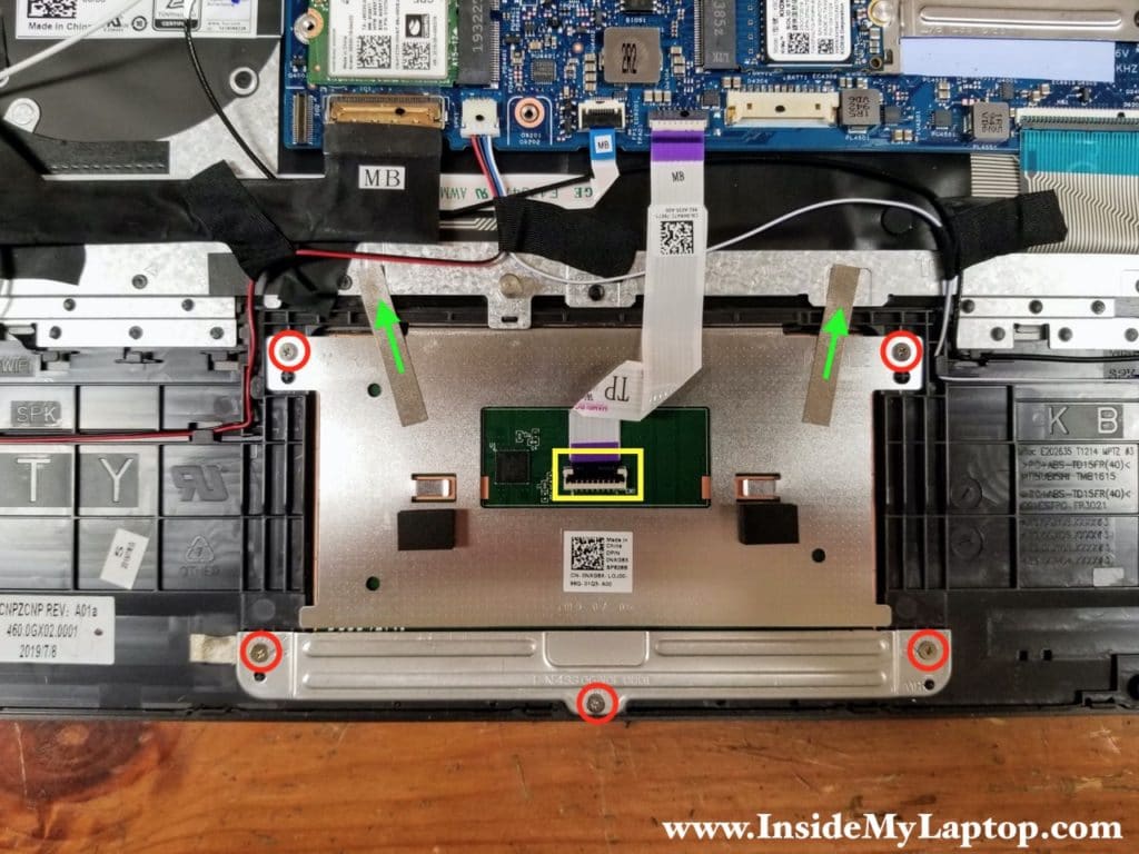
Dell Vostro 5391 trackpad also easily removable. Simply remove 5 screws, disconnect the trackpad cable and peel off grounding tape (treen arrows). After that you can remove the trackpad.
The keyboard, on the other hand, is permanently attached to the top case and cannot be replaced separately unless you want to try this keyboard replacement hack. If the keyboard fails, it’s necessary to replace the entire top case.
