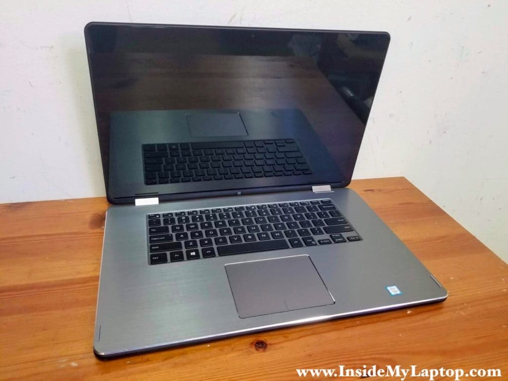
In this post I will walk you through step-by-step Dell Inspiron 15 7568 (model P55F) laptop disassembly procedure.
I will start with removing easily accessible components such as the hard drive, battery, cooling fan and finish with removing the motherboard and display panel.
At the end of this guide you can find a link to the official Dell Inspiron 15 7568 service manual.
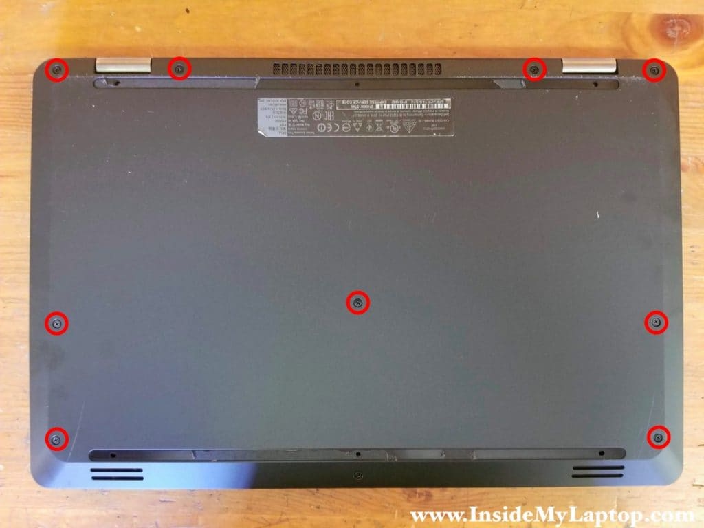
STEP 1.
Remove nine screws securing the base cover.
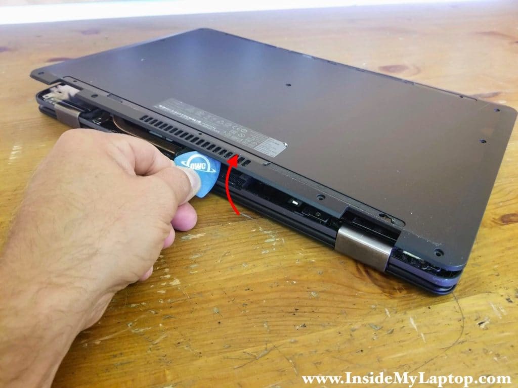
STEP 2.
Start separating the base cover from the top case assembly at the display hinges side.
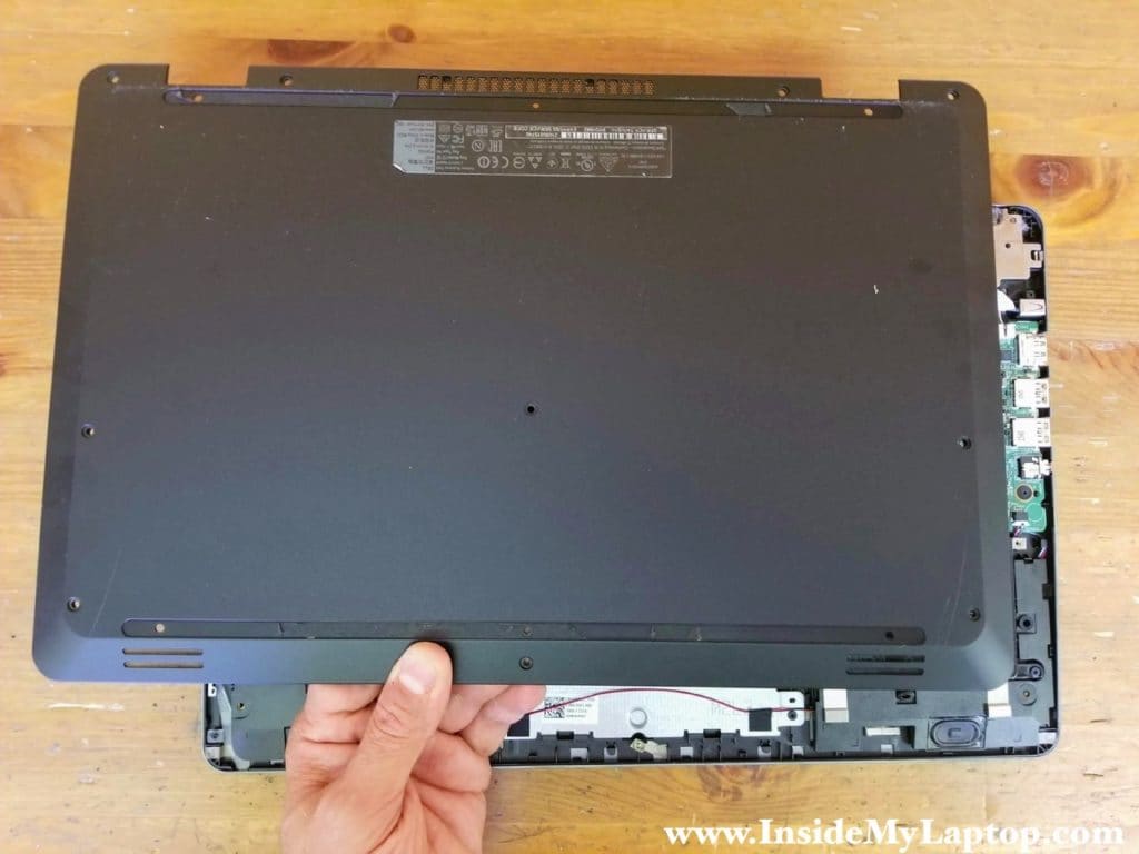
STEP 3.
Remove the base cover.
STEP 4.
Remove four screws attaching the battery to the top case.
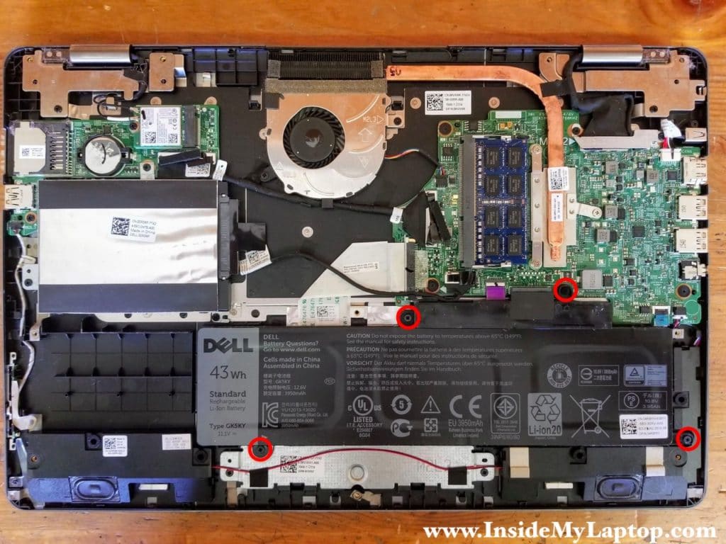
STEP 5.
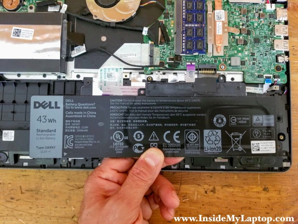
Remove the battery.
There is no cable to disconnect. The battery connected directly to the motherboard.
Dell Inspiron 15 7568 battery model: GK5KY.
STEP 6.
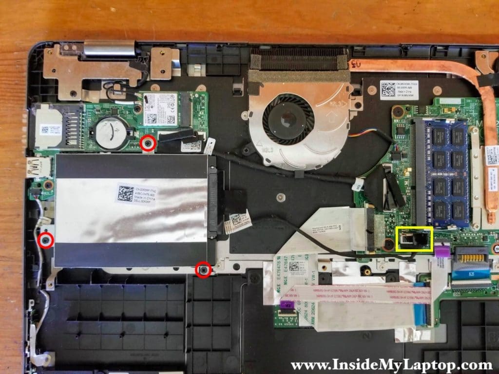
Remove three screws securing the hard drive bracket.
Unplug the hard drive SATA cable from the motherboard.
STEP 7.
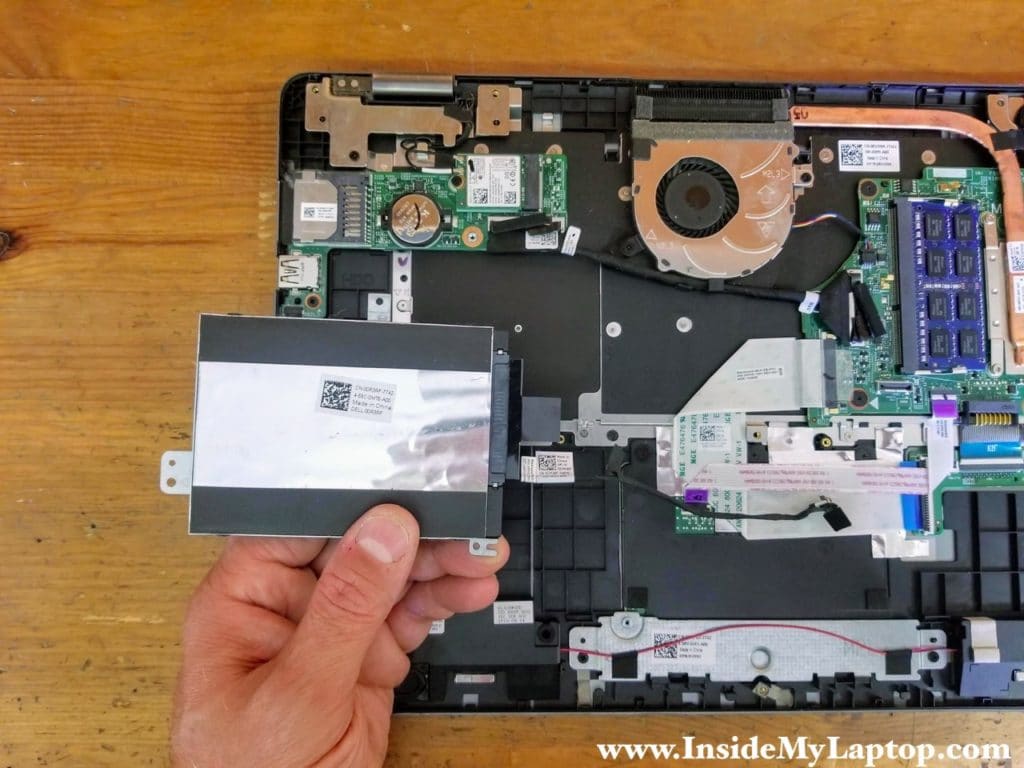
Remove the hard drive assembly with the cable attached to it. Upgrading this hard drive with a 2.5″ solid state drive will improve laptop performance.
There is only one RAM slot on the motherboard. You can install up to 16GB DDR3-12800 SODIMM RAM module in this slot.
STEP 8.
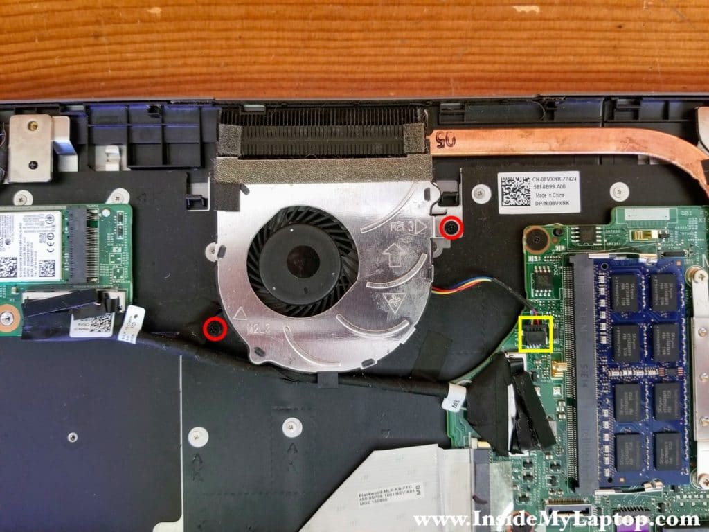
Remove two screws securing the cooling fan.
Disconnect the fan cable.
STEP 9.
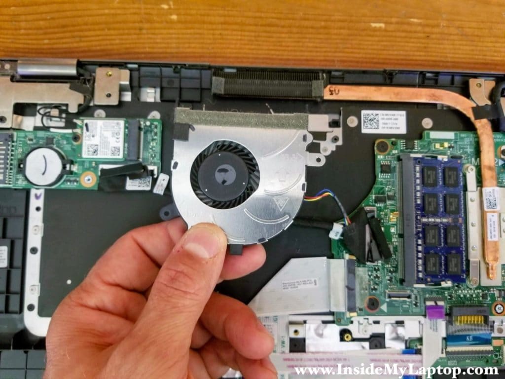
Remove the fan.
STEP 10.
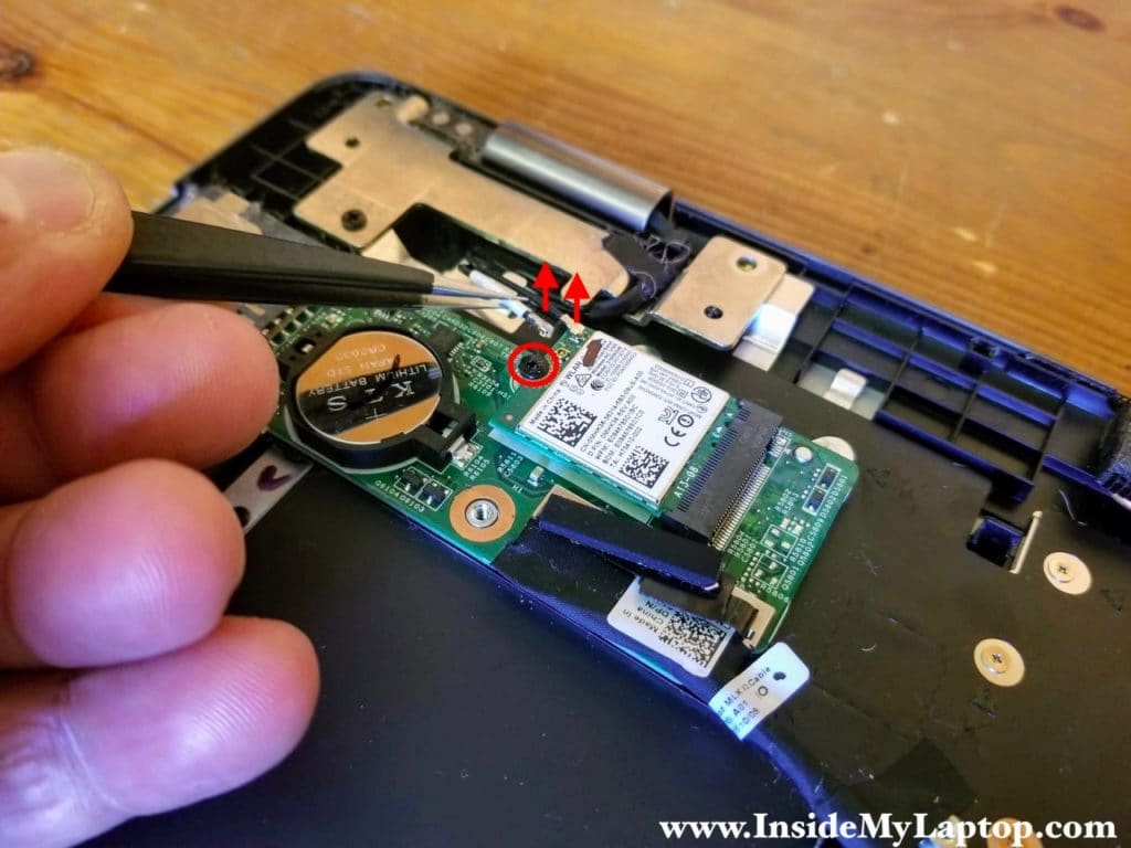
Disconnect two antenna cables from the wireless card.
Remove one screw securing the card.
STEP 11.
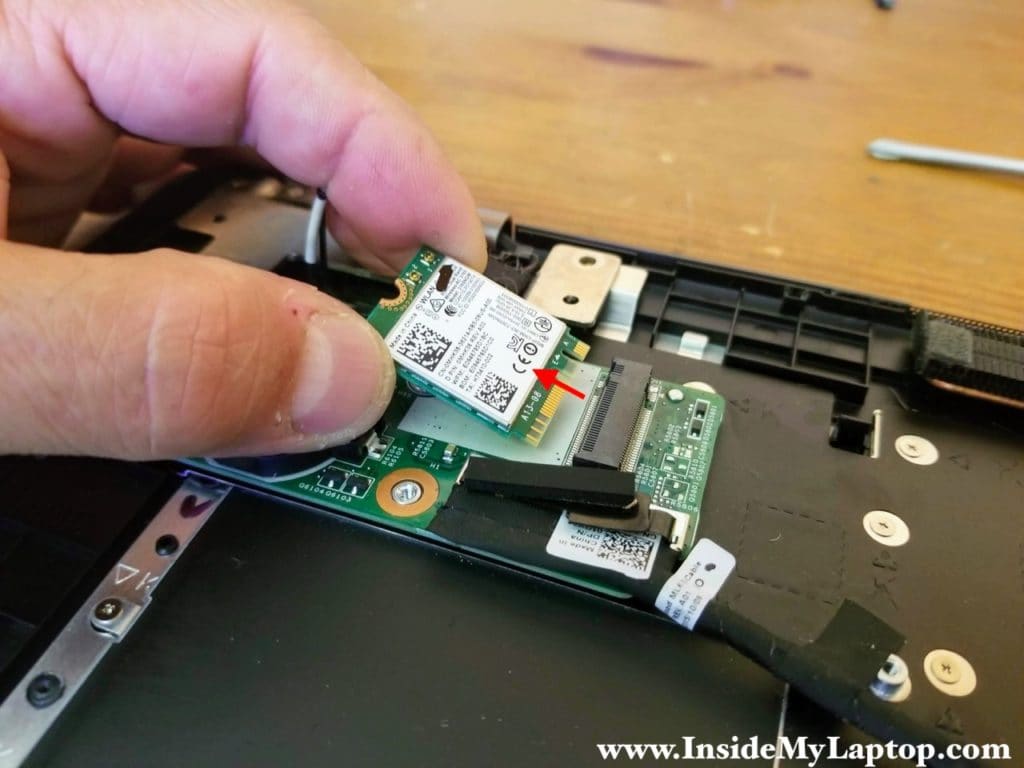
Remove the wireless card.
STEP 12.
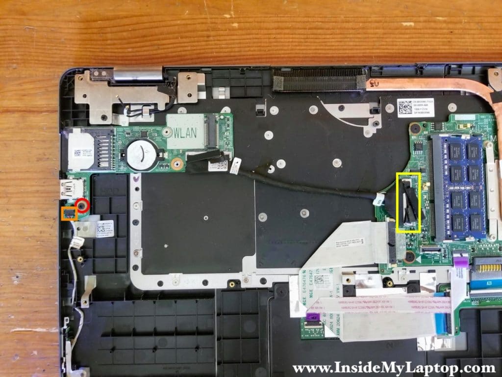
Remove one screw from the USB SD card reader board.
Disconnect the I/O cable from the motherboard (yellow).
Disconnect the speaker cable from the board (orange).
STEP 13.
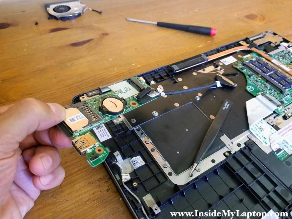
Remove the USB SD card reader board.
As you noticed, the CMOS battery located on that board.
STEP 14.
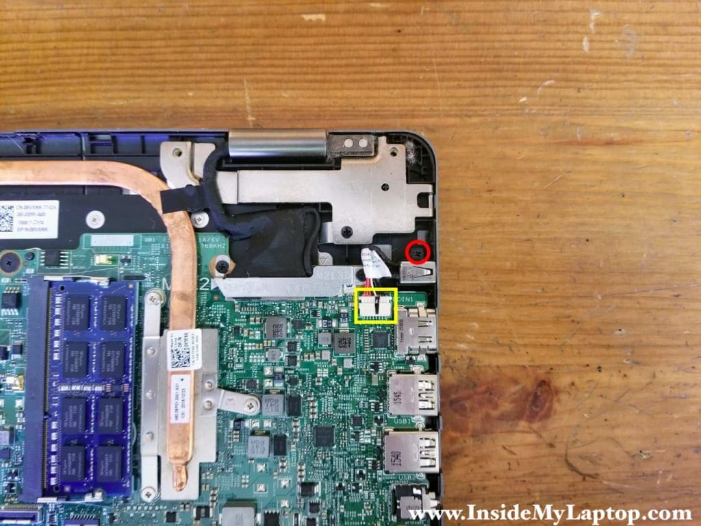
Remove one screw securing the DC power jack.
Disconnect the power cable from the motherboard.
STEP 15.
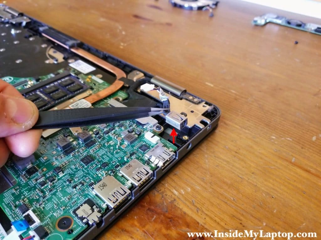
Lift up the DC jack and remove it.
STEP 16.
Remove two screws from the bracket that secures the display cable connector.
Remove the bracket.
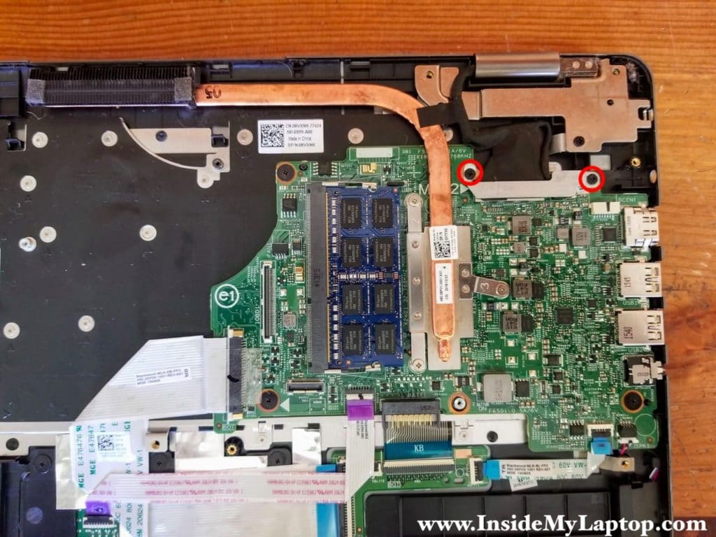
STEP 17.
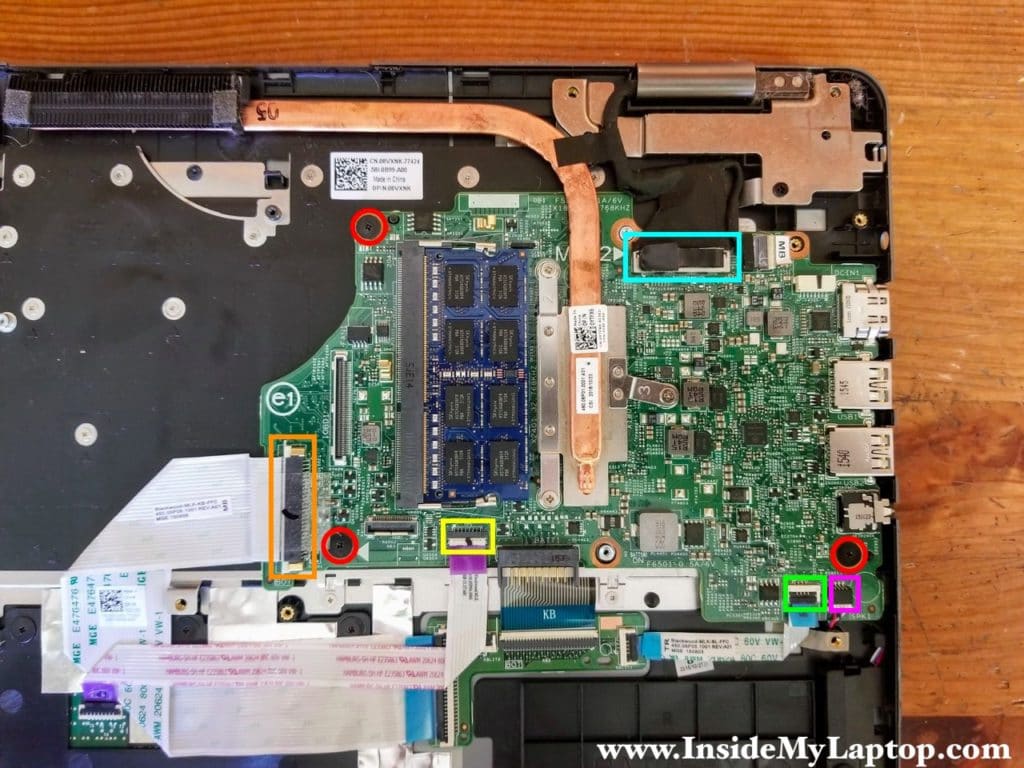
Remove three screws from the motherboard.
Disconnect the following color-coded cables:
– Wide keyboard connector board cable (orange).
– Touchpad cable (yellow).
– Narrow keyboard connector board cable (green).
– Speaker cable (pink).
– Display video cable (blue).
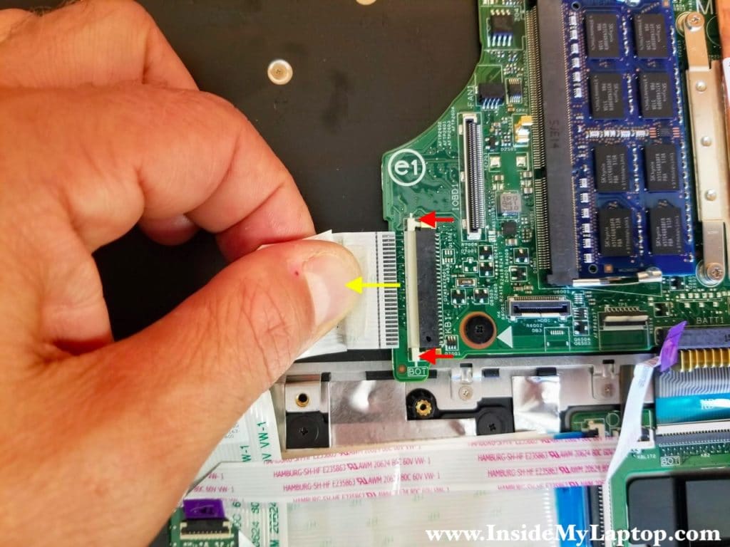
Here’s how to disconnect the touchpad and other cables.
Unlock the connector by lifting up the locking tab (red arrow) and pull the cable out (yellow arrow).

The wide keyboard connector board cable has a different type of connector.
Open up the connector by sliding the locking tab about 2-3 millimeters to the shown direction (two red arrows). Pull the cable out.
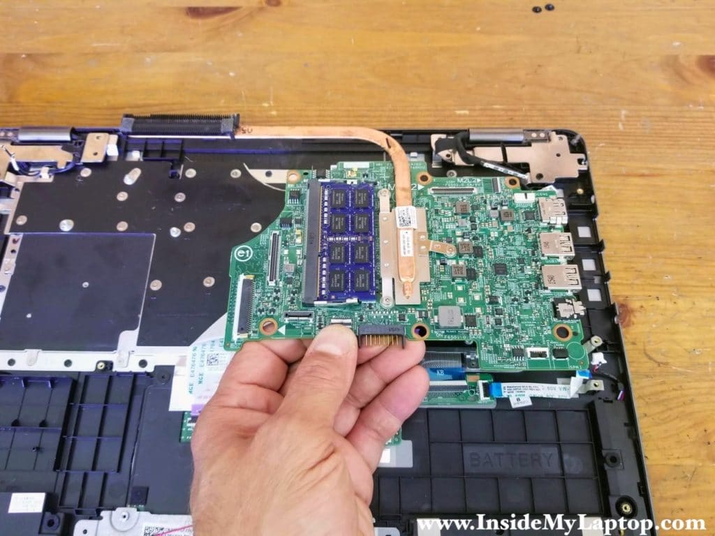
STEP 18.
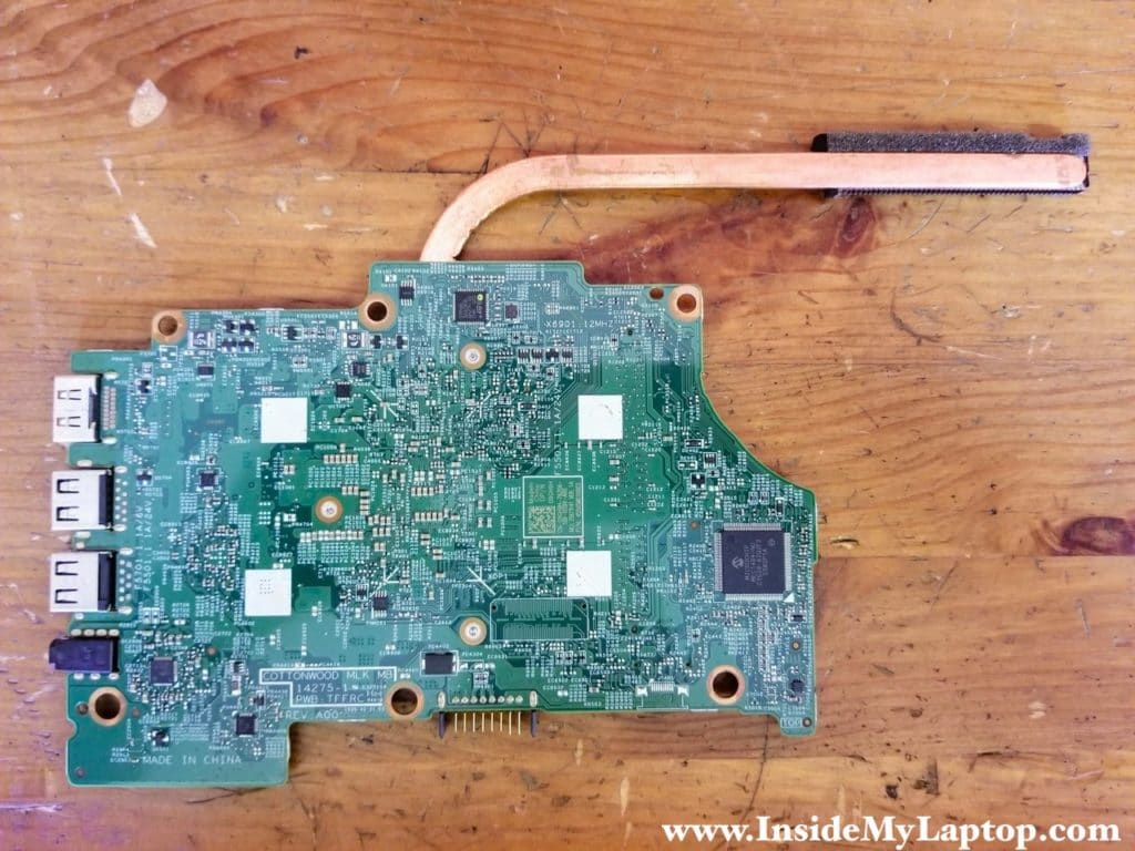
Remove the motherboard.
Here’s a photo of the other side of the motherboard.
STEP 19.
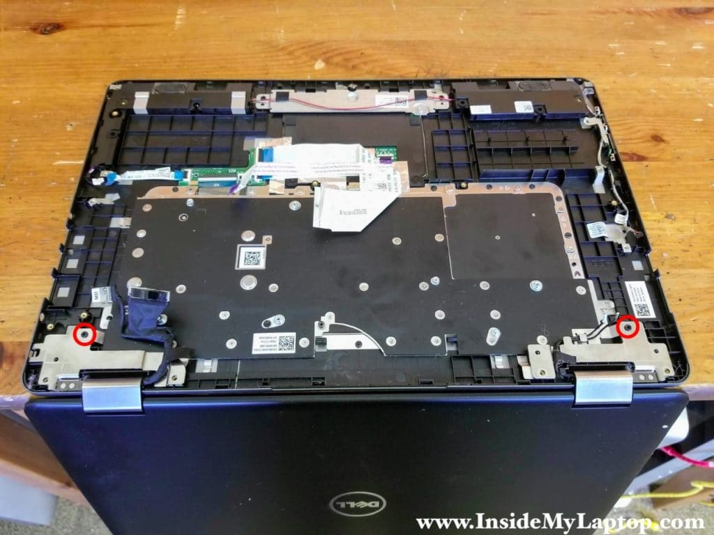
Place the laptop upside down with the display opened on the edge of the desk.
Remove two screws securing display hinges.
STEP 20.
Remove the display assembly.
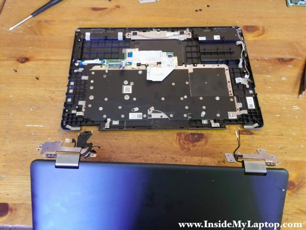
Dell Inspiron 15 7568 keyboard is removable. There are about 30 screws securing it to the top case.

Renae
This is very helpful. Any ideas on why I cannot get the charger to charge the battery? I have replaced the DC jack with a new one as it was broke. I put the battery back in and put cover back on. Plugged in the charger and nothing. The computer still won’t charge. Because the battery is dead, I cannot do any BIOS updates or anything like many others talk about.
IML Tech
Renae, it’s likely the battery is dead and has to be replaced. Does the laptop turn on at all? Does it turn on with the battery disconnected?
Try reconnecting the battery just in case. Maybe the connection between the battery and the motherboard is bad.