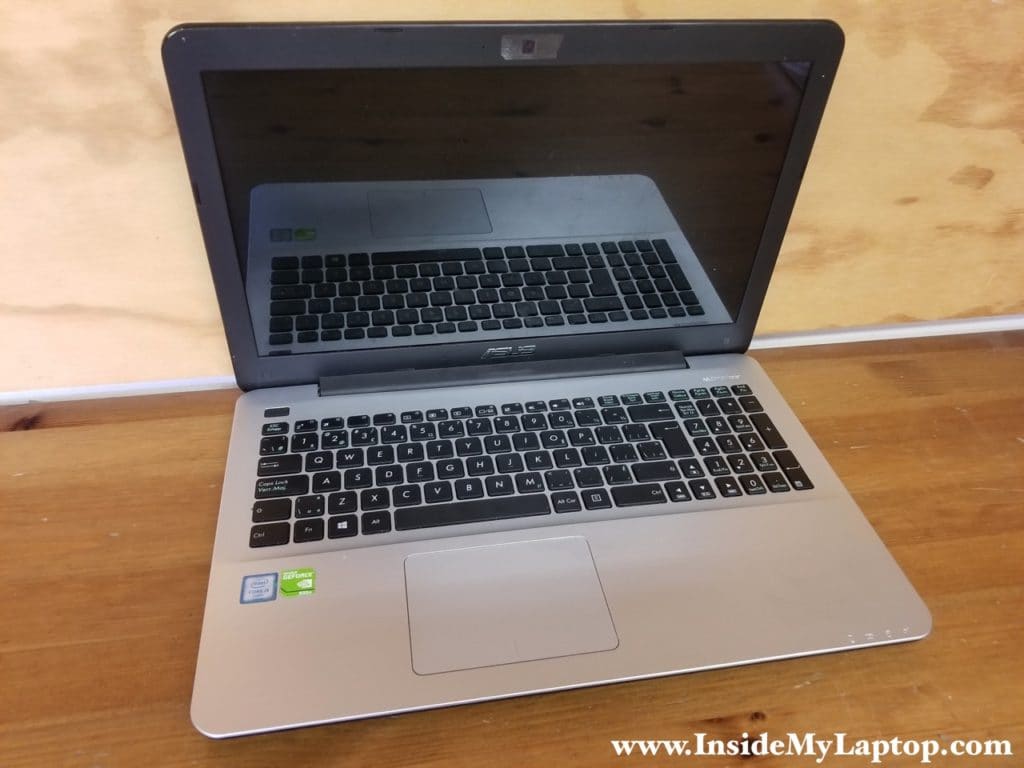
Today I present you a guide for complete disassembly of Asus X555 series laptops. There are many different configuration in this family depending on the hardware specs and country.
You should be able to apply these teardown instructions for the following Asus models:
- X555L, X555LA, X555LB, X555LD, X555LF, X555LI, X555LJ, X555LN, X555LP
- X555U, X555UA, X555UB, X555UF, X555UJ
- X555DA, X555DG, X555QA, X555QG, X555SJ, X555YA
- and more…
In the first part of this guide I will take apart the laptop case and in the second part I explain how to open up the display assembly.
Part 1. How to disassemble laptop case.
STEP 1.
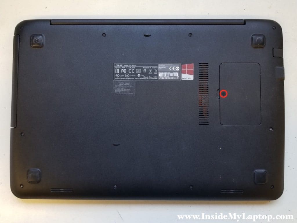
Remove one screw securing the memory cover. The screw is hidden under the plastic sticker which can be removed using a needle. Remove the cover.
STEP 2.
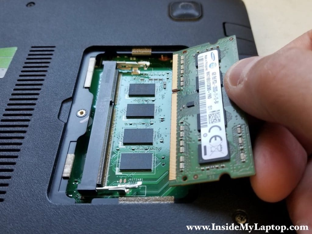
Asus X555 series laptop has only one removable memory module.
You can install up to 8GB DDR3-12800 SODIMM RAM module into this slot.
When you remove the RAM stick, you can see the memory chips integrated into the motherboard.
STEP 3.
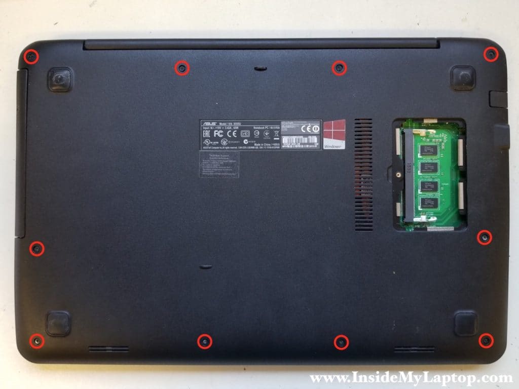
Remove all screws from the bottom.
Warning! These screws have different length. Make notes or draw a diagram of where each screw is located. If you install a wrong screw into a wrong hole, you can damage the case.
STEP 4.
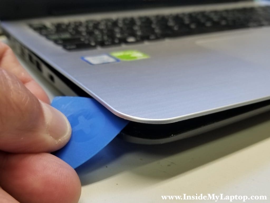
Using a plastic opener pry the top case palmrest assembly up and separate it from the bottom case.
STEP 5.
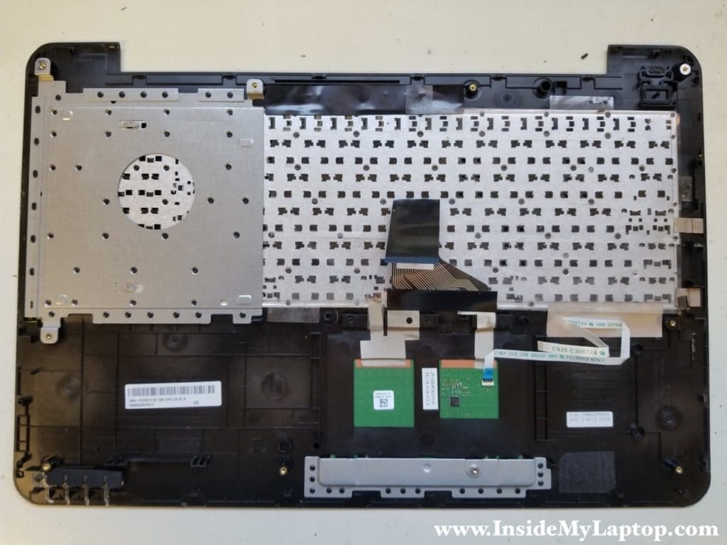
Lift up the top case to access the cables. You will find the keyboard cable and the touchpad cable connected to the logic board.
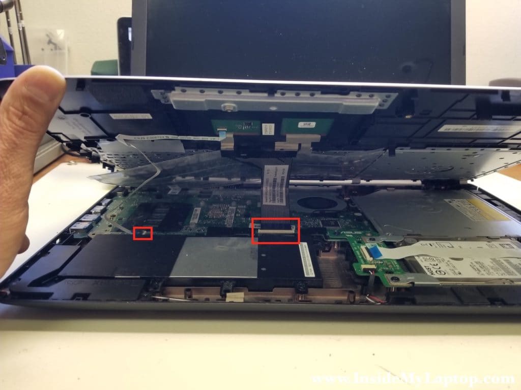
Befor you pull the cable out, it’s necessary to unlock the connector.
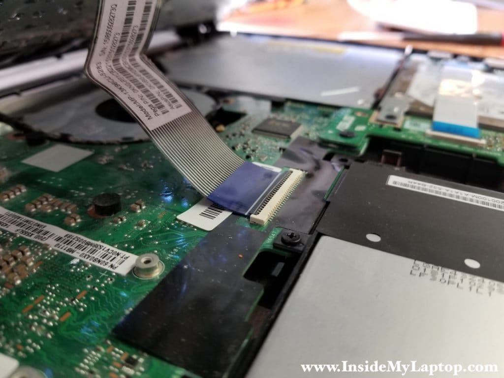
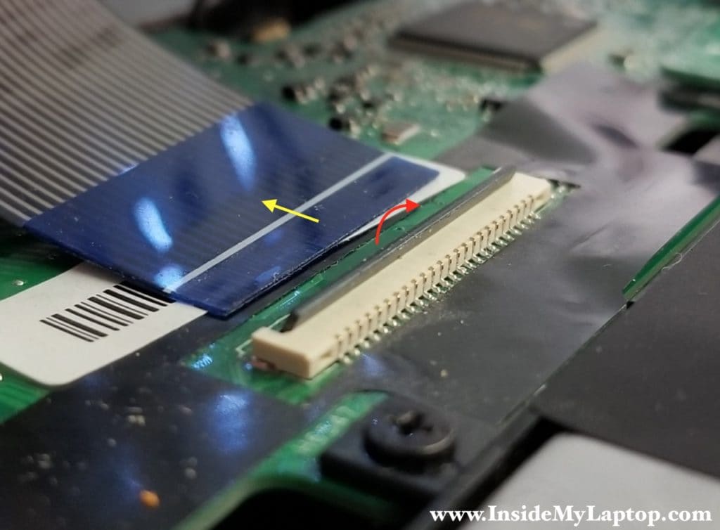
Lift up the locking tab so it opens up at a 90 degree angle (red arrow).
Now, when the cable is released, you can pull it out.
On the other side of the top case you can access the touchpad. The keyboard is riveted to the top case and cannot be easily removed.
STEP 6.
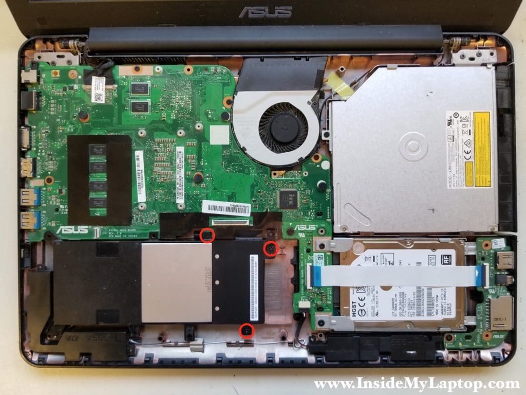
Remove three screws securing the battery.
STEP 7.
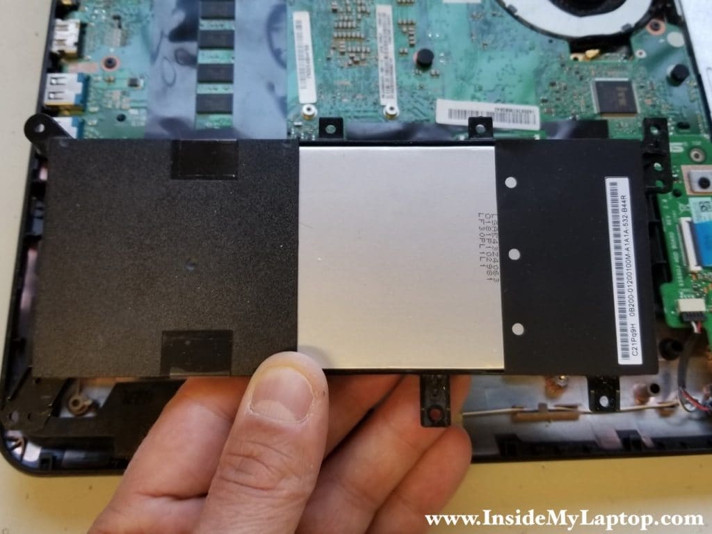
Lift up and remove the battery. Replacement battery model: C21N1347.
STEP 8.
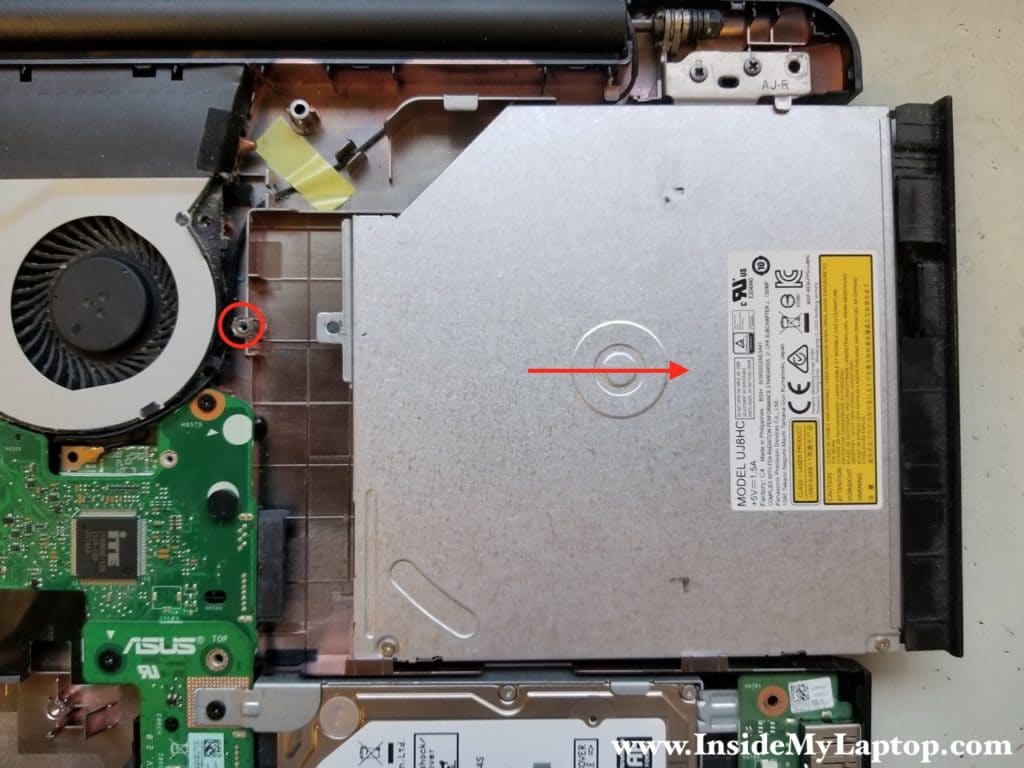
Remove one screw securing the CD/DVD drive. Slide the drive to the right to disconnect it from the motherboard and remove from the case.
STEP 9.
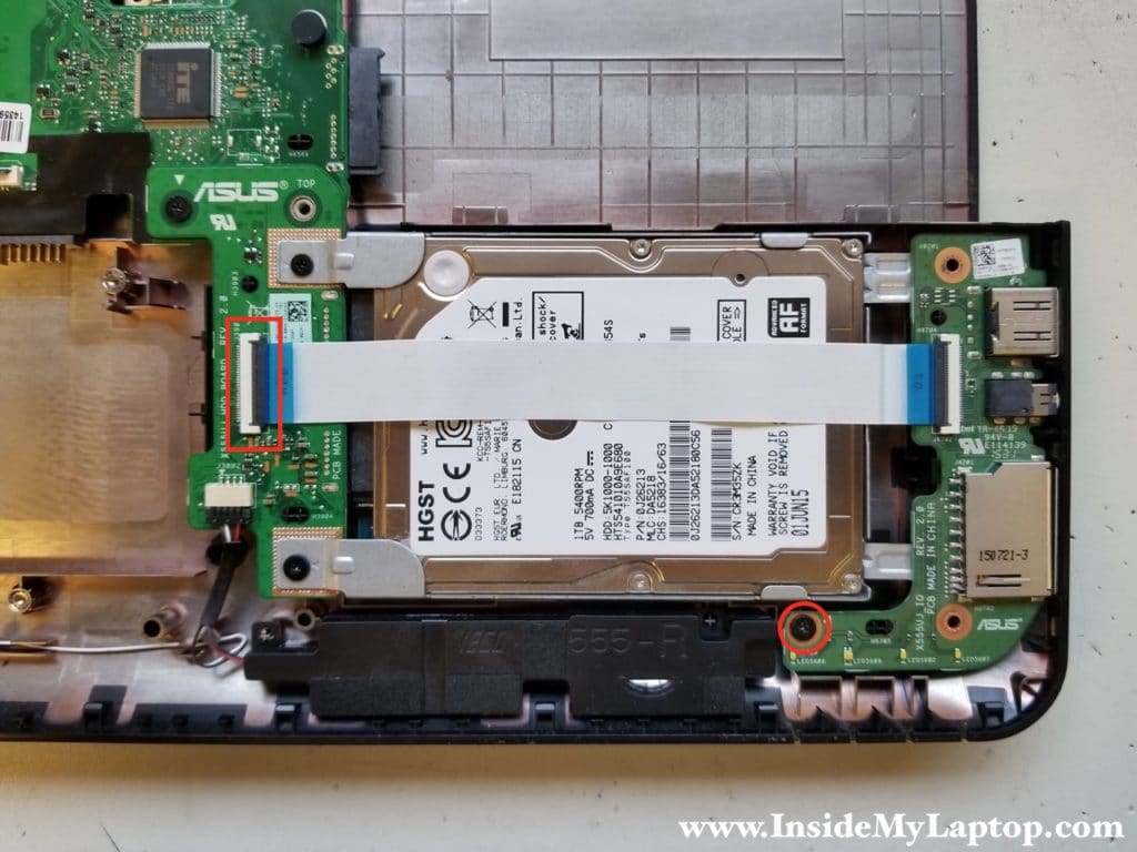
Disconnect the cable from the hard drive board.
Remove one screw securing the I/O (USB / Audio Jack / Media Card reader board).
STEP 10.
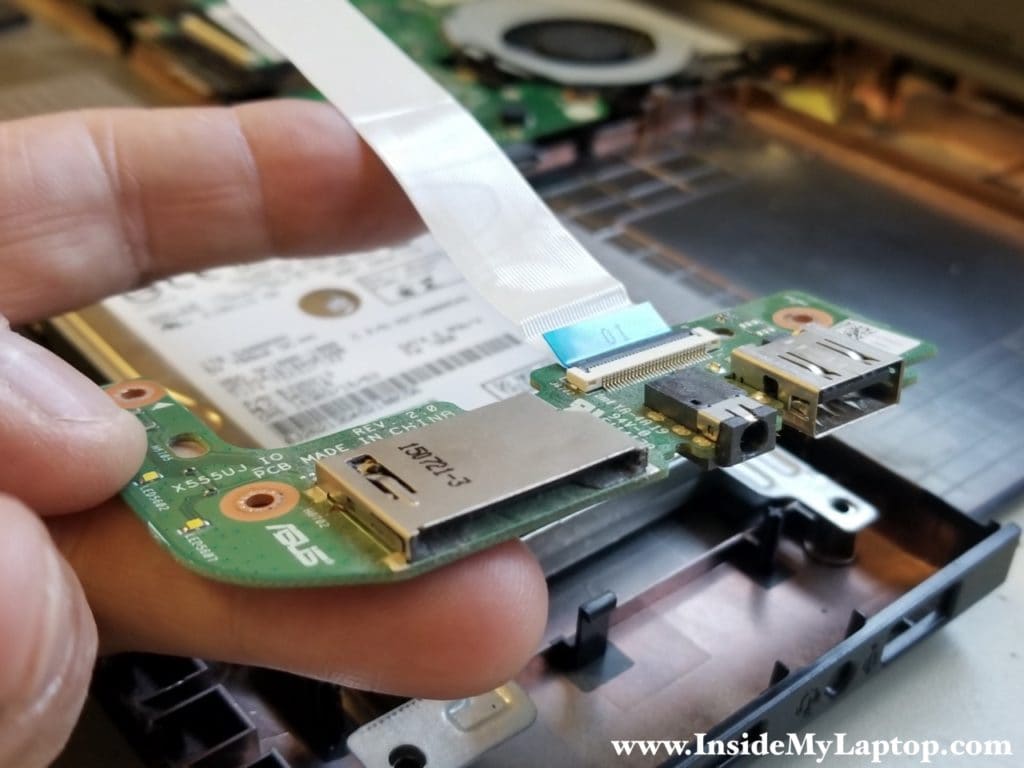
Remove the I/O board with the cable.
STEP 11.
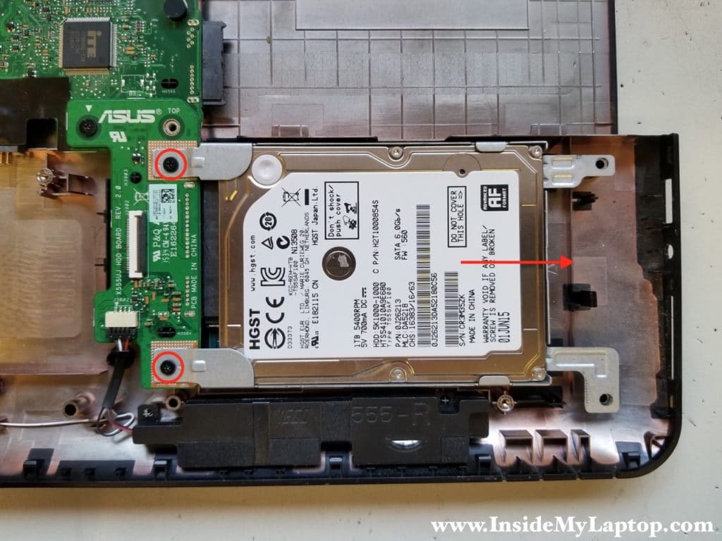
Remove two screws securing the hard drive caddy.
Slide the hard drive assembly to the right to disconnect it from the board and remove it from the case.
Installing a 2.5″ SATA solid state drive instead of this regular hard drive will improve laptop performance significantly.
STEP 12.
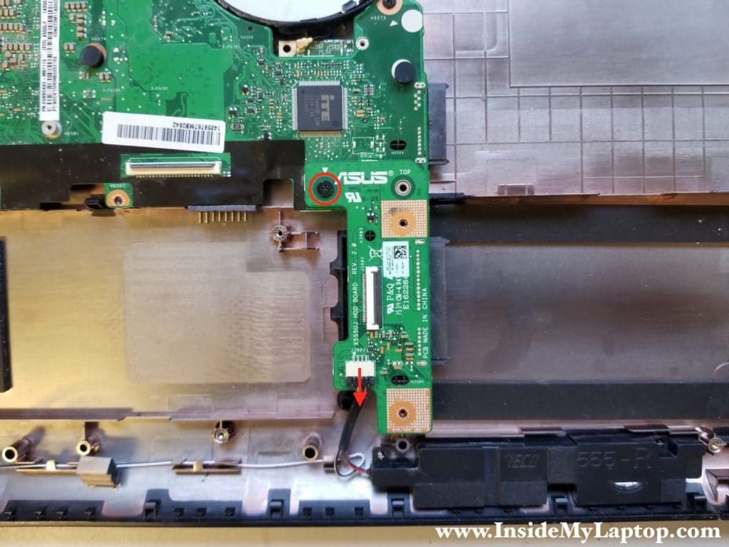
Remove one screw securing the hard drive board. Disconnect the speaker cable.
STEP 13.
Lift up the hard drive board to disconnect it from the motherboard.
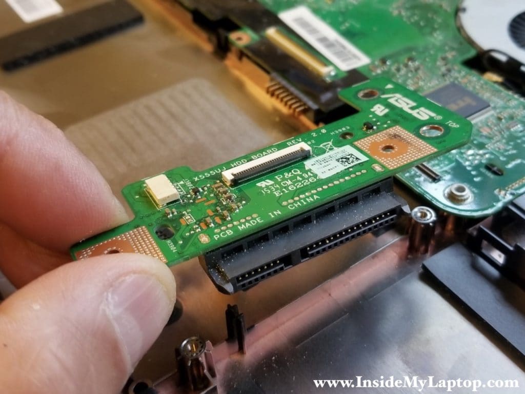
STEP 14.
Unplug the wireless card antenna cable.
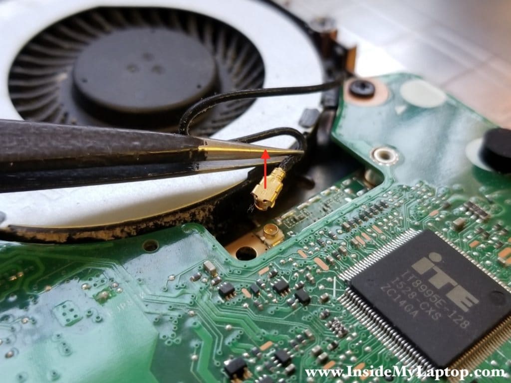
STEP 15.
Remove five screws securing the motherboard. Disconnect the video cable.
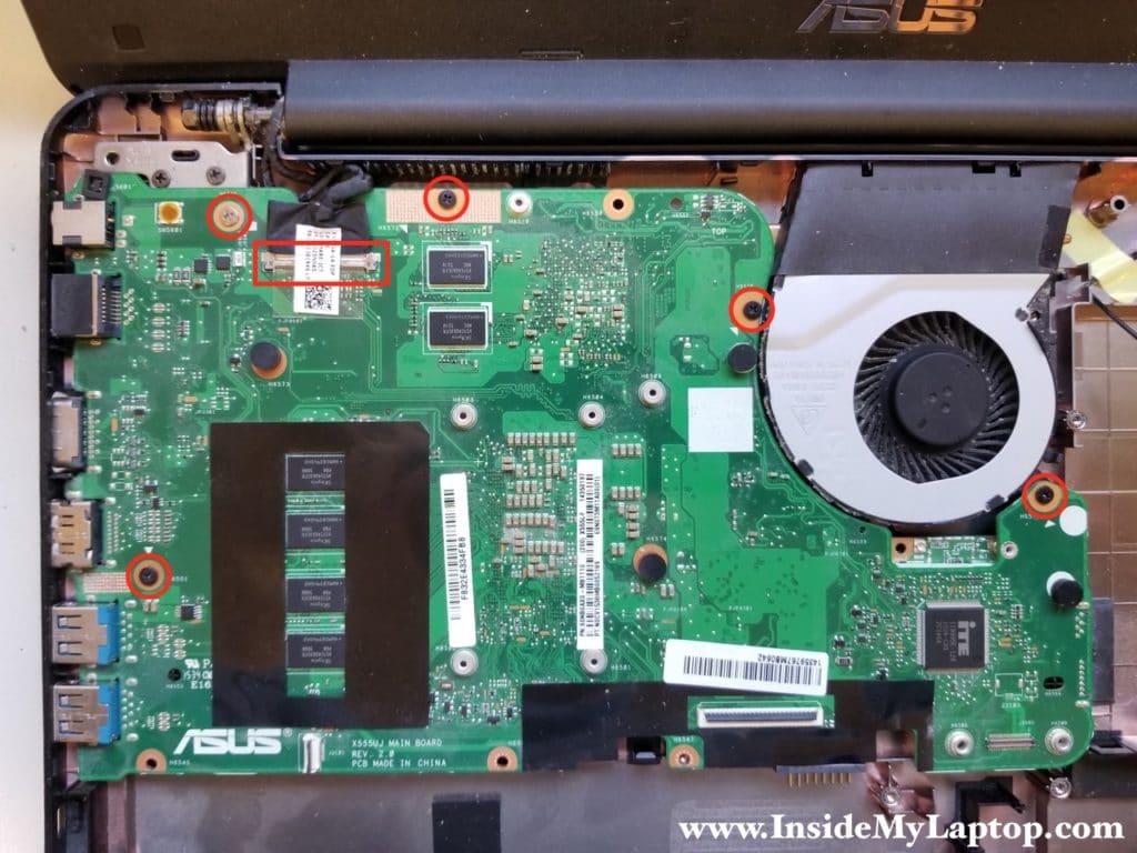
The connection is secured by clear sticky tape. Peel off the tape and unplug the video cable from the motherboard.
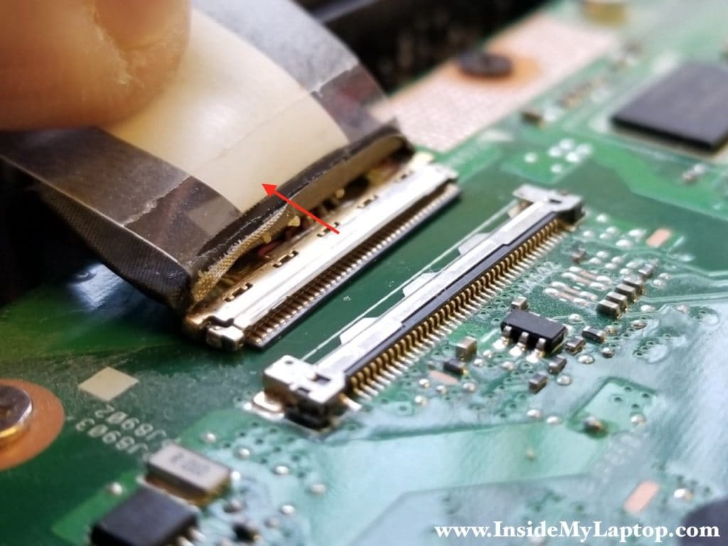
STEP 16.
Remove the motherboard from the bottom case.
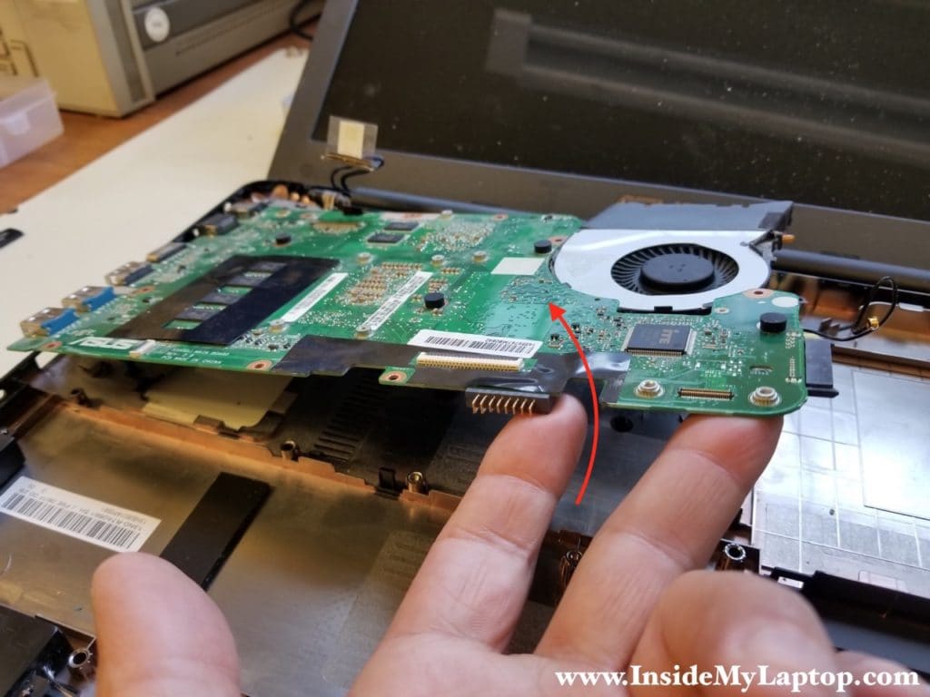
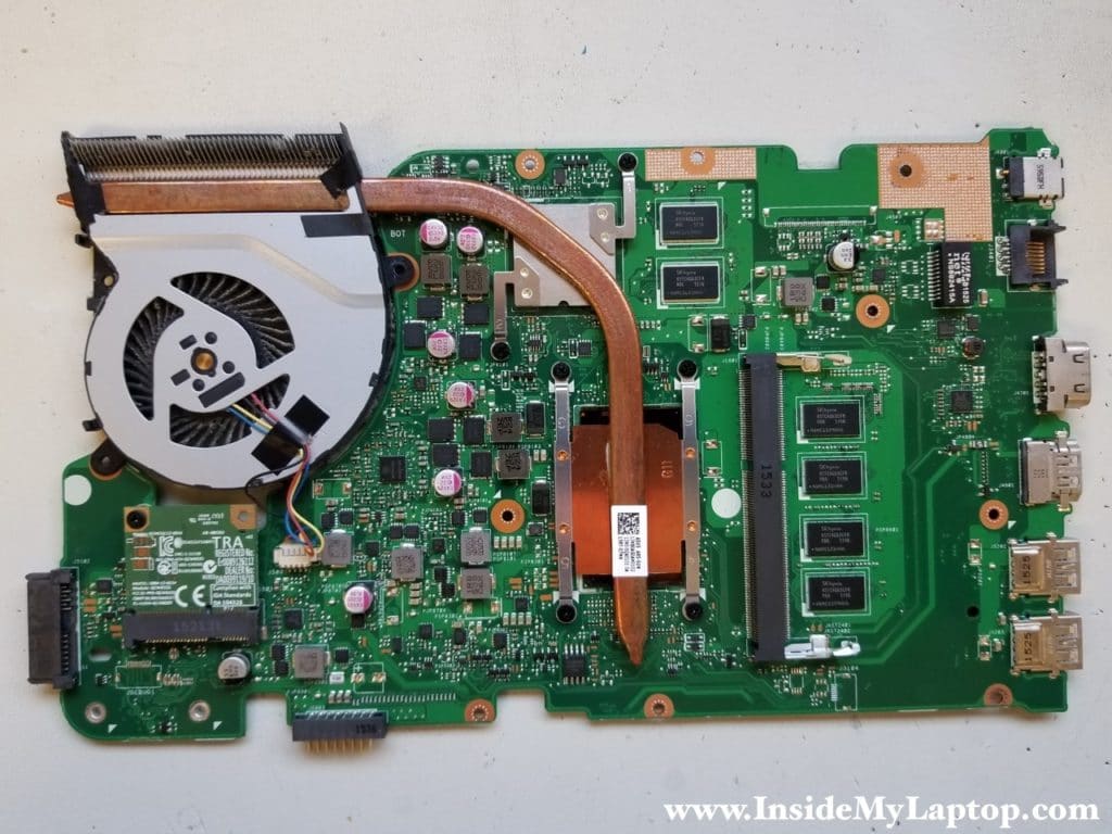
On the other side of the board you can access the cooling module (heatsink and fan) and the wireless card.
The DC power jack is soldered to the motherboard.
Part 2. Display assembly and screen removal.
In Asus X555 series laptops the display assembly cannot be taken apart until it’s removed from the bottom case.
You can use this part of the disassembly guide for accessing and replacing the LCD screen, display hinges, video cable and webcam.
STEP 17.
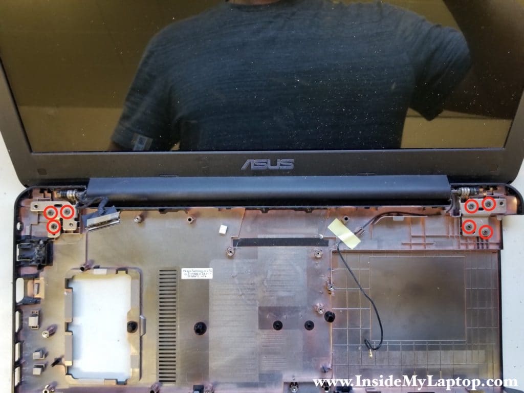
Remove all screws securing the display hinges and separated it from the bottom case.
STEP 18.
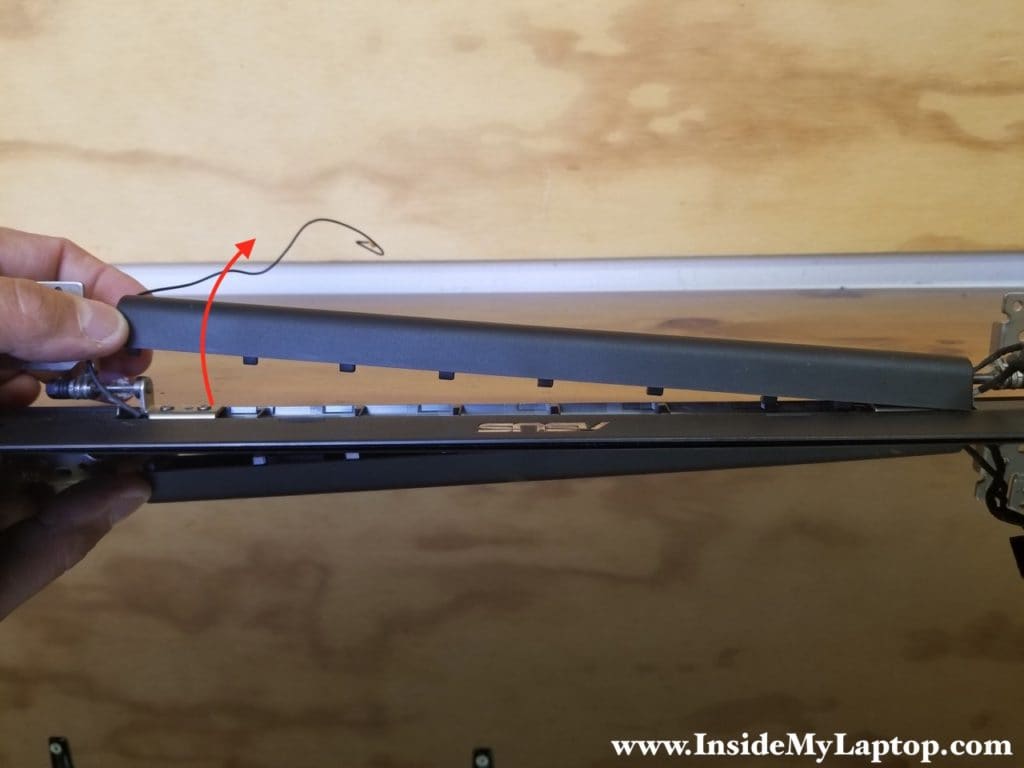
Slide the hinge cover to the shown direction.
It can be done only when the display is out of the case.

STEP 19.
Remove the hinge cover.
STEP 20.
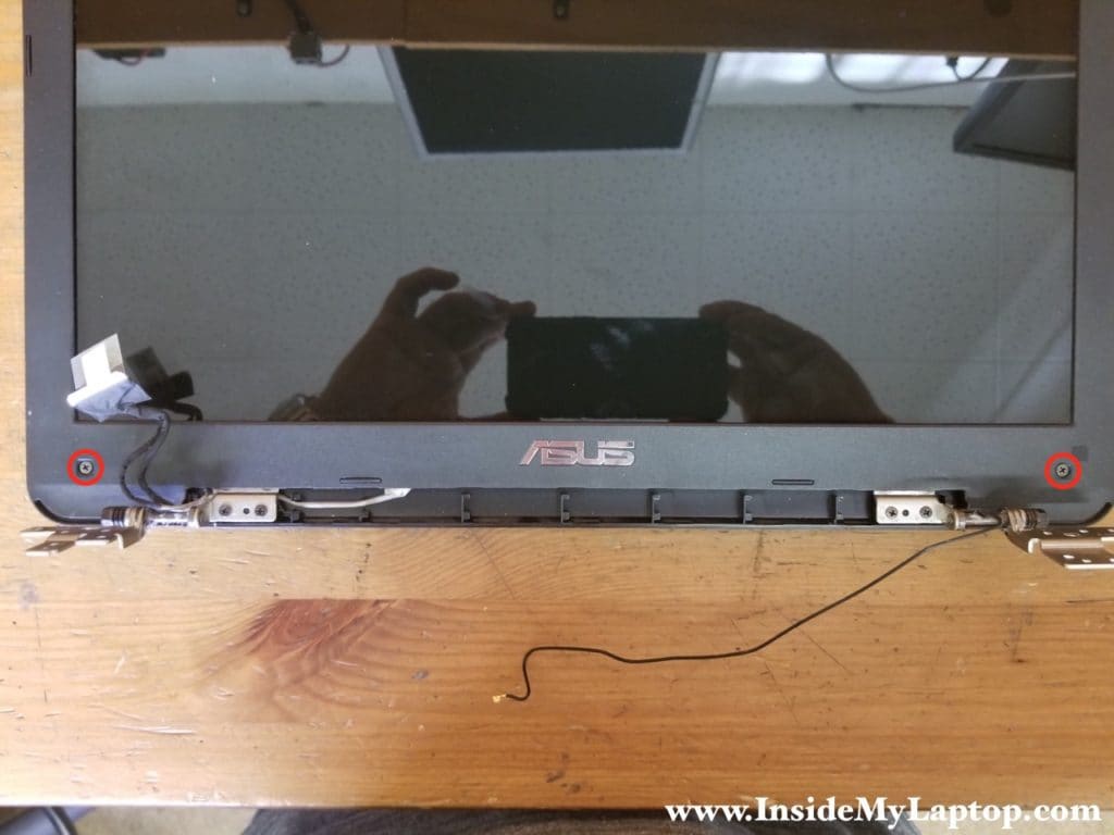
The screen bezel has two screws on the bottom. They are hidden under plastic covers. Remove both screws.
STEP 21.
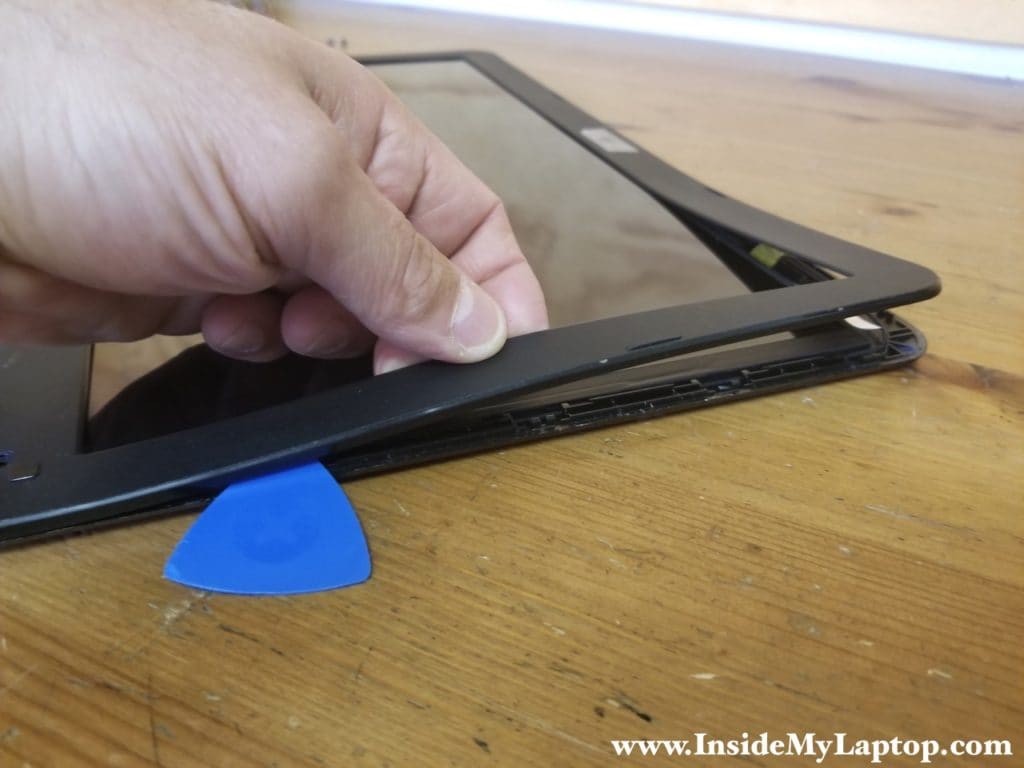
Now you start separating the screen bezel from the back cover. A plastic case opener tool will be helpful.
STEP 22.
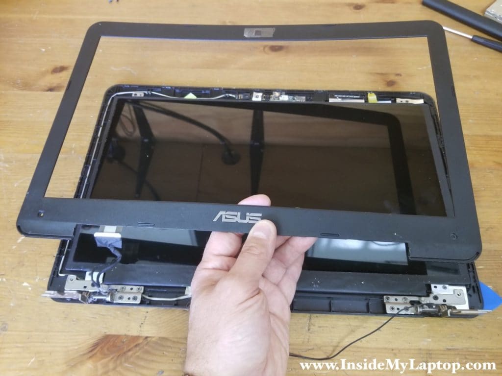
Remove the bezel.
STEP 23.
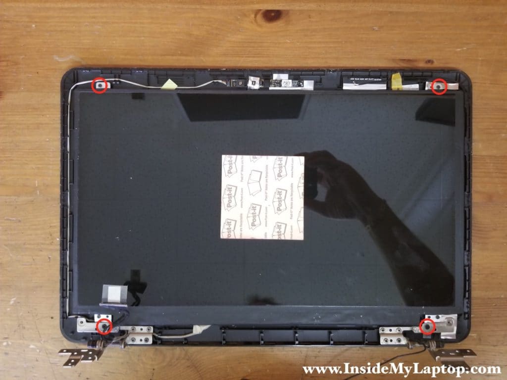
Remove four screws securing the LCD screen to the display back cover.
STEP 24.
Remove the screen from the cover and place it the front side down on the desk. Now you can access the video cable.
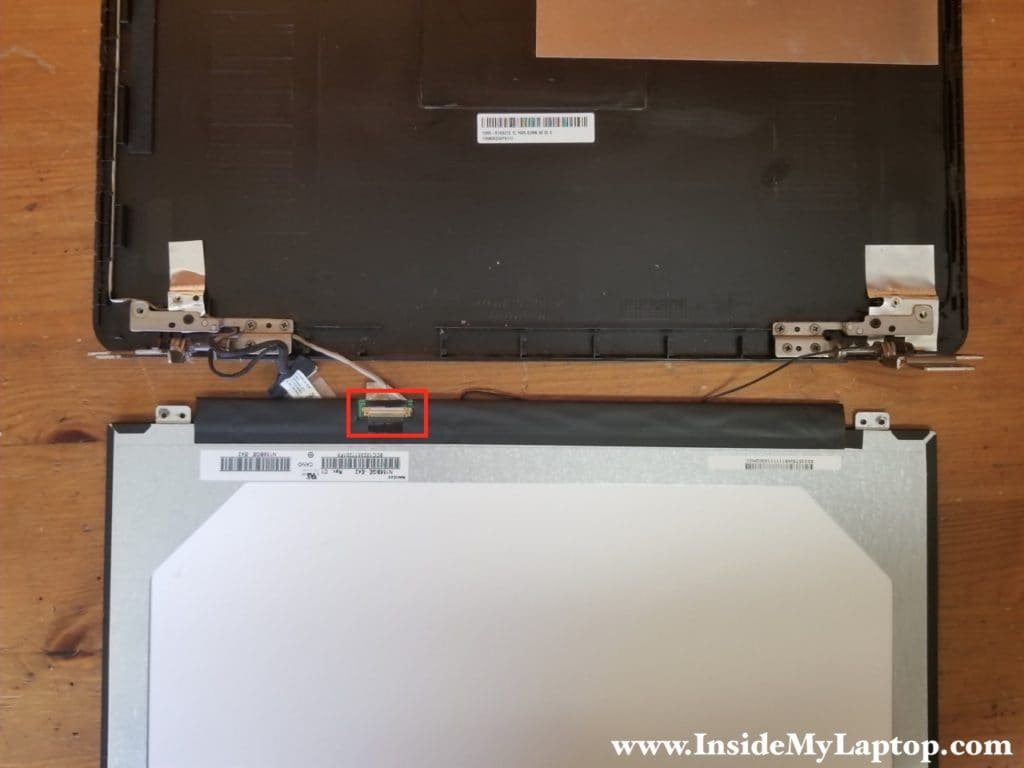
STEP 26.
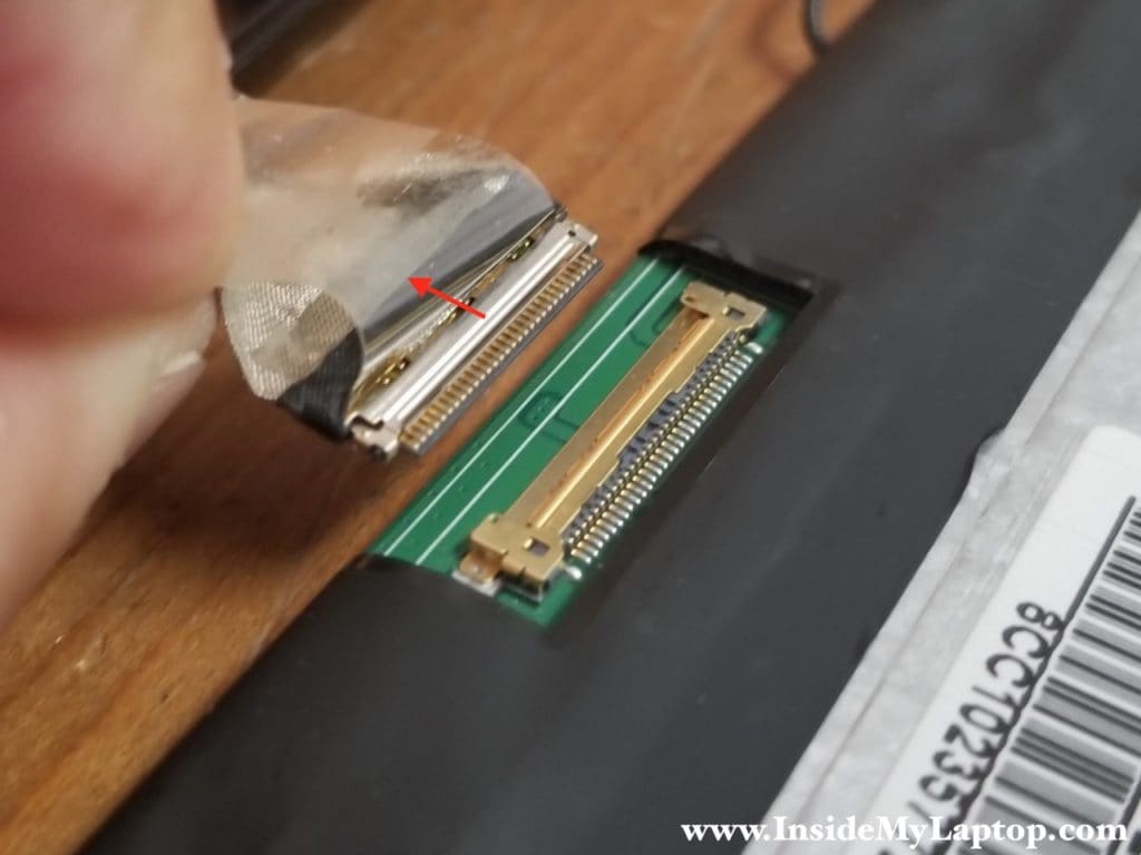
Peel off clear tape securing the connection and unplug the video cable from the screen.
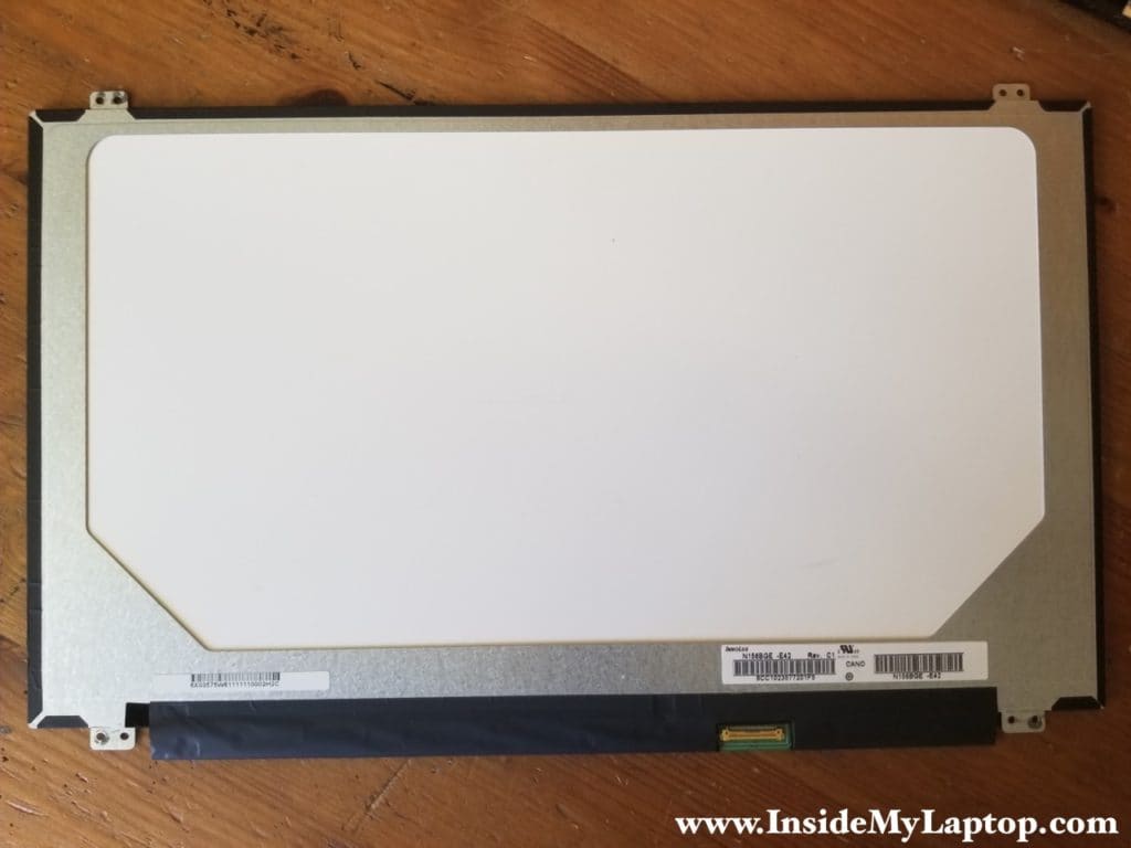
You can search for a replacement screen using the model number which is printed on the back. In my case the screen model is N156BGE-E42.
Victor Waller
I’ll be replacing fan next week. Do you recommend any particular thermal grease? What do you use?
IML Tech
@ Victor,
I use MX-4 Arctic Thermal Compound.
Rujul Hitendra Desai
Do you have any information about size of the screws? I lost two of them and want to install.
Dav
I need to trace power sequence from EC chip. F555uj ver 2.0. Only got 3.3 5v and 1.05 volt. Other coils show zero. And no 0 ohm shorts. Schematic?
I’m suspecting. ec chip
benglist
can you locate the CMOS battery? i want to reset my BiOS because i did wrong setting and now my notebook going blank screen.
Matthias U
There’s no CMOS battery. Why would a laptop have one? If the main battery ever is low enough to no longer power the RTC, keeping the CMOS settings is the least of your worries.
Remove the main battery, leave it for a few minutes, short the connector, leave for another few minutes, reassemble.
Rob
When you say short the connector in order reset cmos, could you provide more details, unfortunately my daughter powered off my laptop during bios update, now wont turn on and no lights showing although adaptor is working fine.
Your details and break down is the best I have found so far, although for me i found after i had already stripped the laptop down.
Rob
Could you elaborate on which connectors to short?
Spartaco
Thank you for your impressive description; i need your help for tell me how can i find the Audio device for to check if is installed with cable. The problem is that in Windows the system say me : disable( red x on audio)
Tom
Do you respond and answer these questions?
IML Tech
@ Tom, not anymore. I still keep the website life and approve comments once in a while but I don’t actively participate in creating new content or answering questions.
Say thank you to Google for screwing small publishers like me. 🙂
Dav
I need to trace power sequence from EC chip. F555uj ver 2.0. Only got 3.3 5v and 1.05 volt. Other coils show zero. And no 0 ohm shorts. Schematic?
I’m suspecting. ec chip
Yannick Le Villain
Hello,
Thank you for your tutto, it is very helpfull.
I have to change my touchpad because of a bad intervention of those idiots of the IT department who broke the connector of the touch pad.
My problem lies in the two plaited metal sheets that seem stuck on it.
Can you tell me what to do next?
ASUS X555YA
A very gratefull thank you for your help,
Y@nnick
MathieuKielson
Thanks for the deets, mate. Thought I’d have to do a complete disassembly to clear the CMOS and reset the BIOS, so I did. Couldn’t find the CLRTC jumper or a CMOS battery, then the solution was in the comments.
For what it’s worth, Google brought me here, and this page more than any other helped to resolve my issue. Saved my PC from being a worthless brick. Much love.
IML Tech
Thank you! Happy to help.
Matthew Hicks
Very useful guide. I needed to upgrade the wifi-card as well as run a 2nd antenna lead behind the screen & used the instructions/images above. I did notice that some of the screws in the guide were not present in my specific laptop & a few others were present that weren’t included in the above images. I do not believe it was due to a newer fab run, but instead installation variations on the factory floor. There is a place for a 2nd antenna on the left side of the screen, but was probably left out under the notion of “savings” when its more a “right to repair” & upgrade deterrence.
Iskren
I would like to correct you the Realtec sound chip is located on the hard drive board, The one on I/O is Realtec card reader chip.
IML Tech
Thank you. I meant to say USB / Audio Jack / Media Card reader board.