
In this guide I am taking apart a MSI GS73VR gaming series laptop model MS-17B1. It’s possible these instructions will work for some other MSI GS models.
I will show how to access the main NVMe SSD and both RAM slots hidden on the bottom side of the motherboard.
STEP 1.
Remove all screws from the base cover.
I color-coded all screws by their length. Make some notes so you install them correctly when you reassemble the laptop.

STEP 2.
Remove the bottom cover. It separates easily.
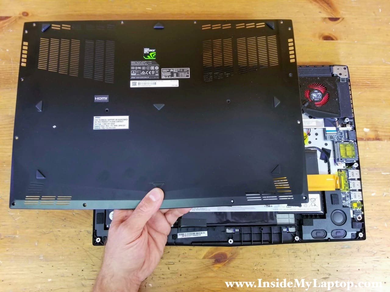
The battery is mounted under the USB audio board cable so it has to be removed first.
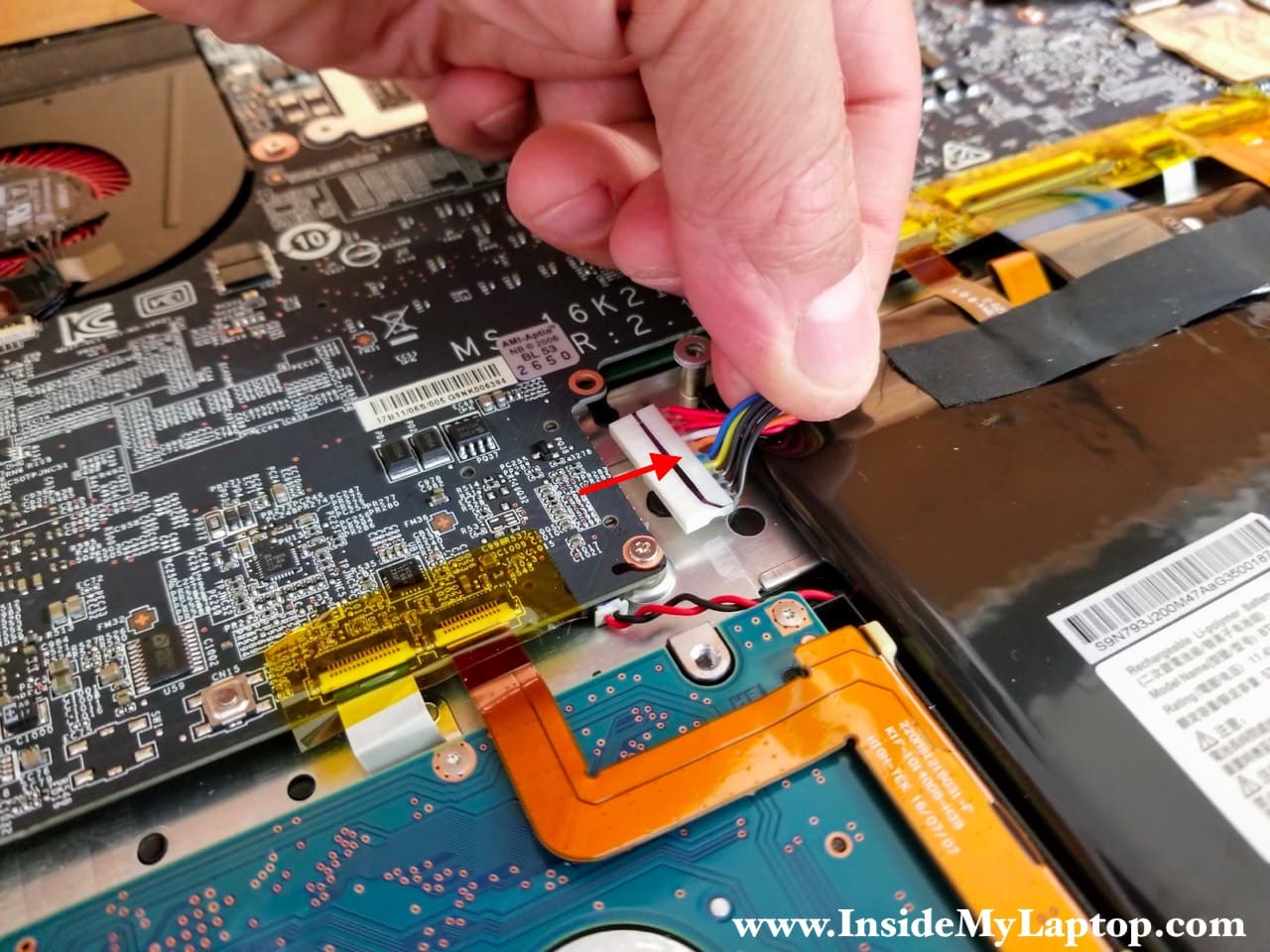
STEP 3.
Disconnect the battery cable from the motherboard. The connector is hidden on the bottom side but it’s easily accessible.
STEP 4.
Remove two screws from the USB audio board.
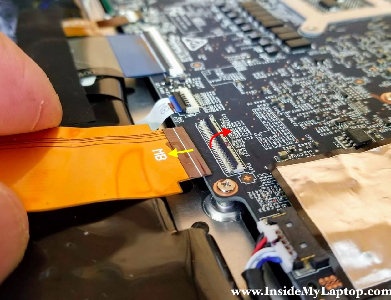
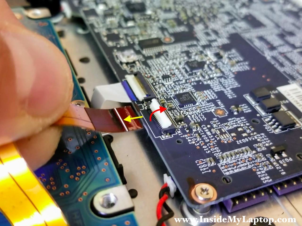
Disconnect the flat cable from the motherboard.

Here’s how to disconnect the cable.
Unlock the connector by lifting up the locking tab (red arrow). After the cable is released, pull it out.
STEP 5.
Remove the USB audio board with the cable attached to it.

STEP 6.
The keyboard cables are taped to the top side of the battery.
Peel off the tape and separate the cables from the battery.

STEP 7.
Remove the battery.
MSI GS73VR laptop has the battery glued to the top case by adhesive tape. You’ll have to apply some reasonable force to take it out.
Replacement battery model: BTY-M6J.

STEP 8.
Disconnect the 2.5″ hard drive SATA cable from the motherboard.

Unlock the SATA connector first (red arrow) and pull the hard drive cable out.
STEP 9.
Remove the hard drive with the cable attached to it.
Replacing this drive with a 2.5″ SATA solid state drive will speed up the system.

STEP 10.
Lift up the right speaker. It’s just seated on a few guide pins.
Disconnect the speaker cable from the motherboard.

STEP 11.
Remove the left speaker.

STEP 12.
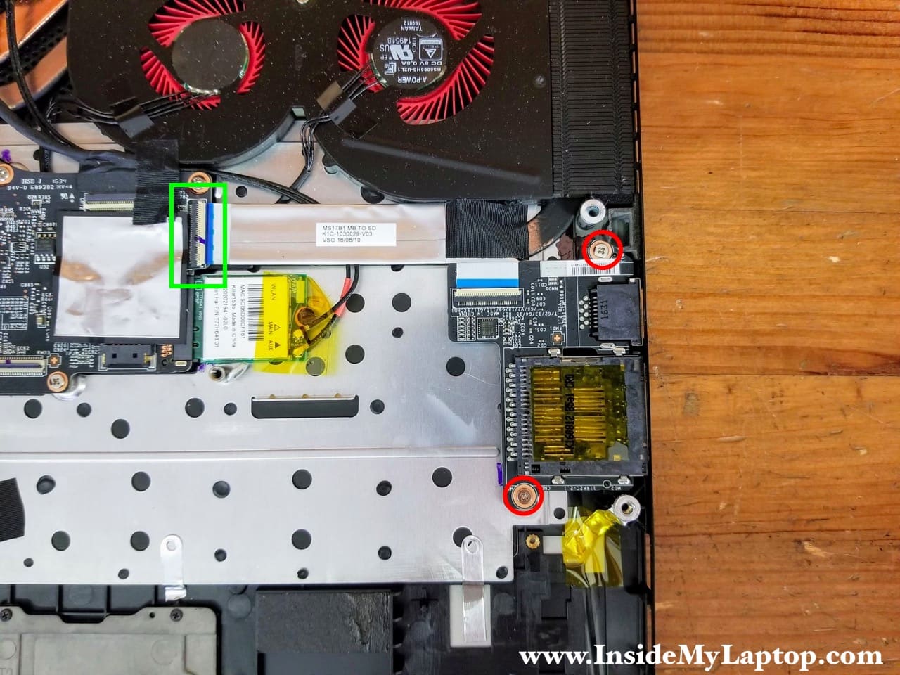
Remove two screws securing the LAN/SD reader board.
Disconnect the flat cable from the motherboard.
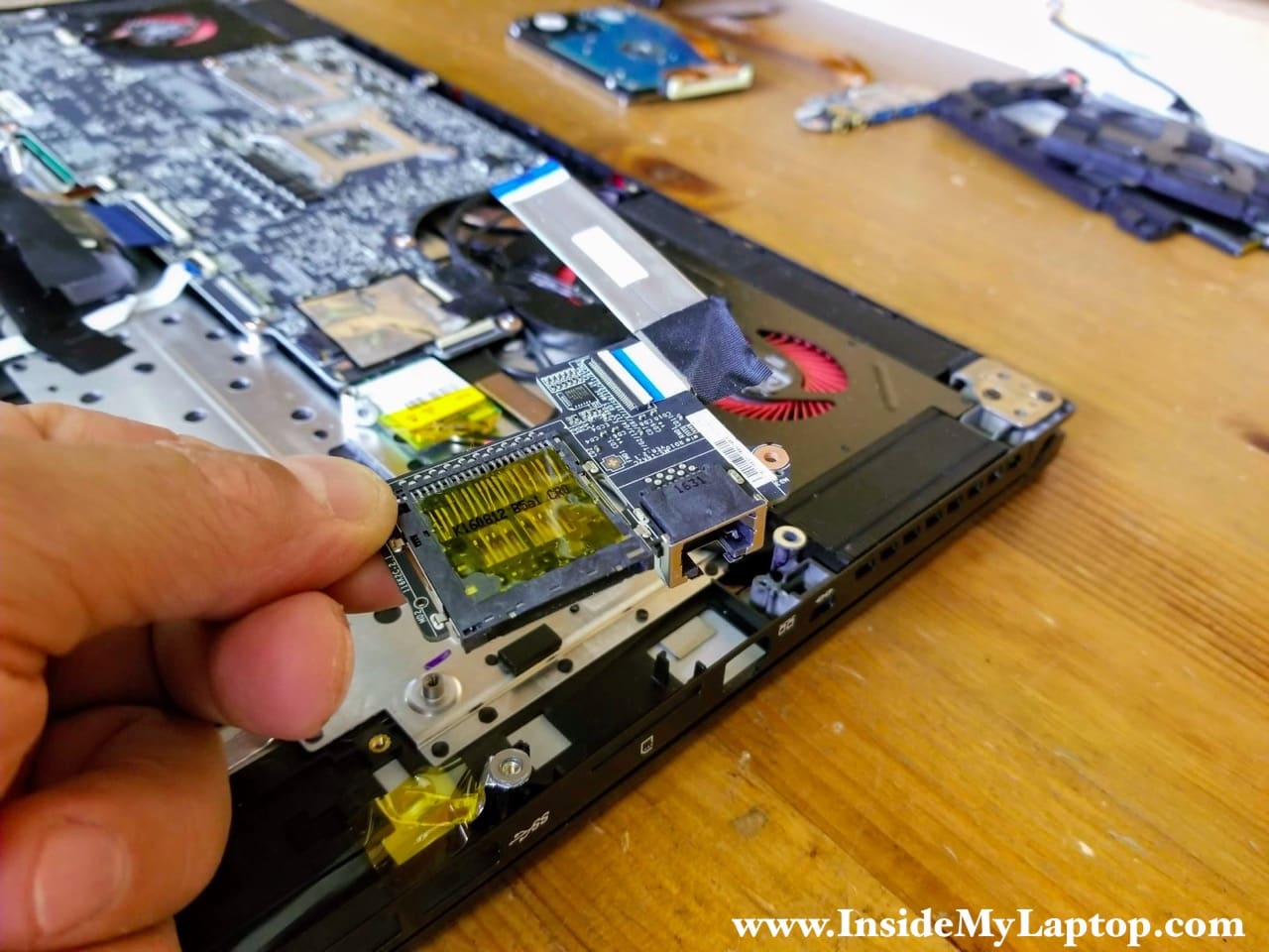
STEP 13.
Remove the LAN/SD card reader board.
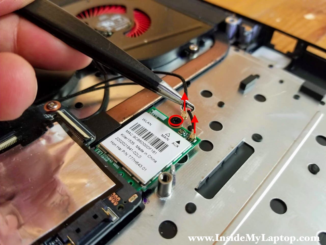
STEP 14.
Disconnect both antenna cables from the wireless card.
Remove one screw securing the wireless card to the top case.
STEP 15.
Pull the wireless card out and remove it.

STEP 16.
Disconnect the display video cable from the motherboard. As always, unlock the connector first and pull the cable out.

STEP 17.
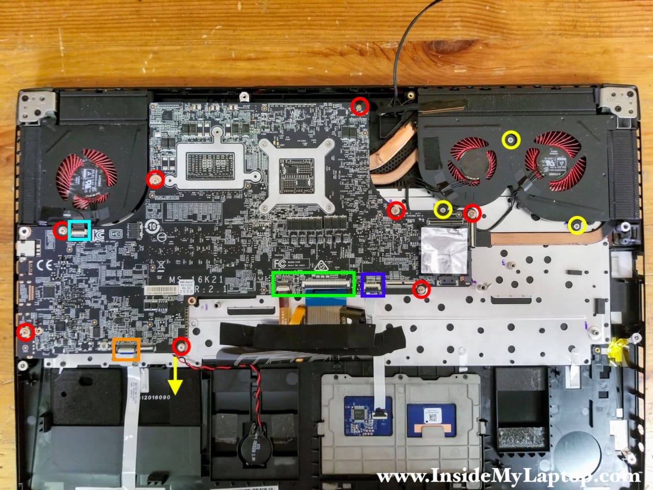
Remove eight screws securing the motherboard (color-coded in red).
Remove three more screws securing the fan assembly (color-coded in yellow).
Disconnect the following color-coded cables:
– Power button board cable (light blue).
– Front LED board cable (orange).
– CMOS battery (yellow arrow). The connector located on the other side of the motherboard.
– Keyboard and keyboard backlight cables (green).
– Touchpad cable (dark blue).
STEP 18.
Start separating the motherboard from the top case.

Be careful with the power button board cable. It’s routed between the right fan and motherboard.

When removing the motherboard slide the cable in the gap between the fan and motherboard.

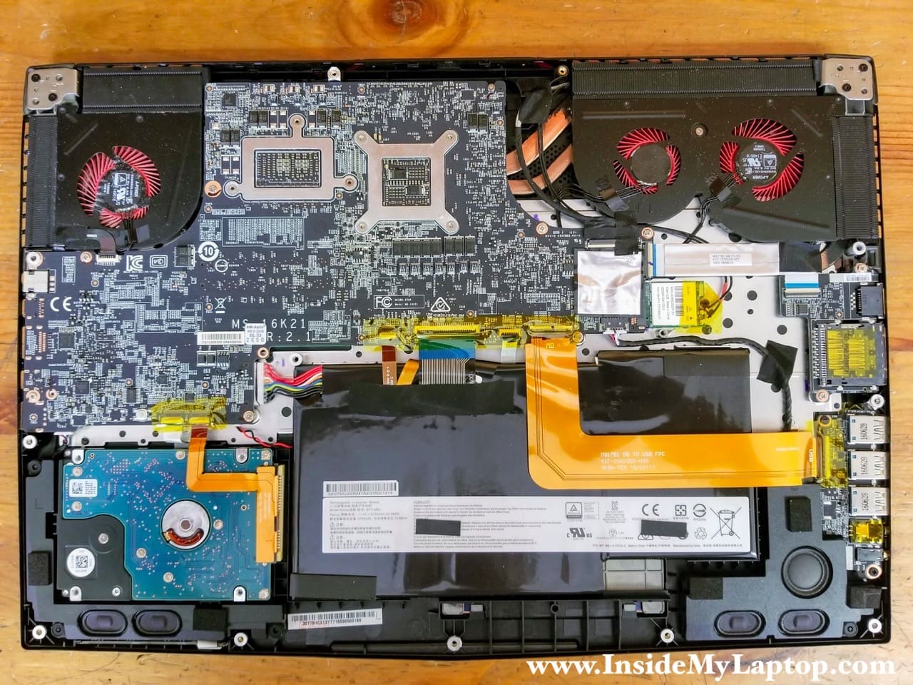
STEP 19.
Remove the motherboard from the laptop.
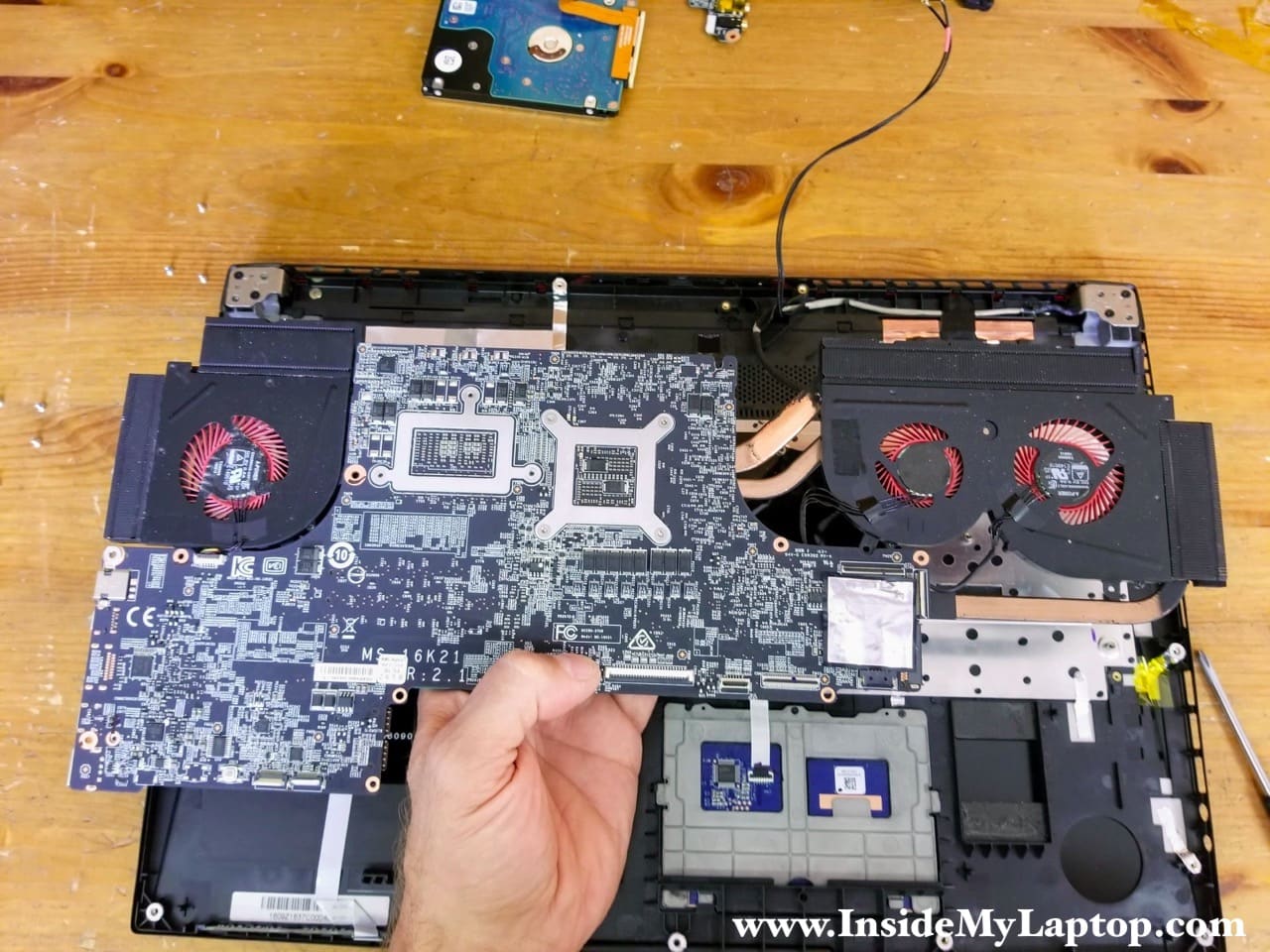
Here’s a view at the top case assembly with the motherboard removed.
In MSI GS73VR laptop the keyboard is permanently riveted to the top case but the touchpad can be removed and replaced if necessary.

Here’s the bottom side of the motherboard.
Both RAM modules and main SSD mounted on this side.
This laptop can handle up to 32GB (2x16GB) DDR4 2400/2666/3200 SODIMM RAM modules and it uses m.2 NVMe PCIe solid state drive.

STEP 20.
Remove one screw securing the NVMe SSD and pull the drive out.

In MSI GS73VR laptop the DC power jack is soldered to the motherboard.
