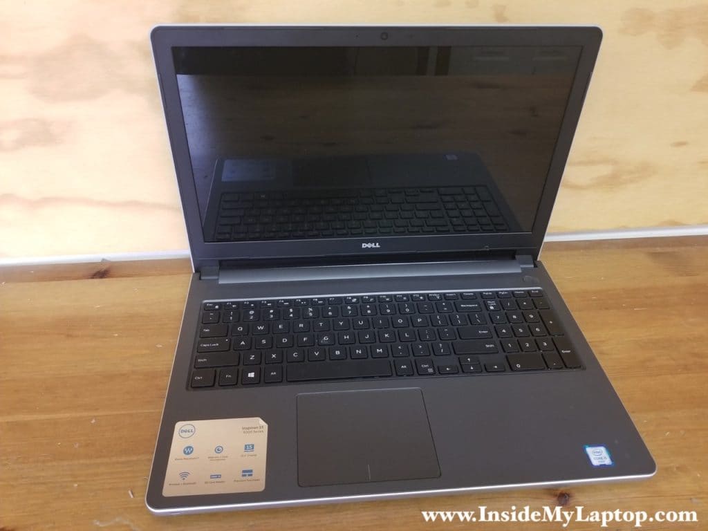
In this guide I will show how to disassemble Dell Inspiron 15 5000 Series laptop.
As an example I’m taking apart a laptop with product name: Dell Inspiron 5559 but also it should work for Dell Inspiron 5558 and 5555.
In this guide I’ll go through the following major steps:
- Removing the battery, hard drive, memory and optical drive: STEPS 1-8.
- Removing the keyboard: STEPS 9-13.
- Removing the bottom case: STEP 14-19.
- Removing the motherboard, DC power jack and cooling fan: STEP 20-27.
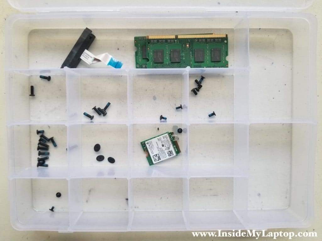
It’s a long disassembly guide so be organized. Keep track of screws.
STEP 1.
Unlock and remove the battery.

STEP 2.
Remove two screws from the hard drive and memory cover.

STEP 3.
Remove the cover.
You’ll have to apply some reasonable force to separate the cover from the bottom case. There are hidden latches securing the cover.

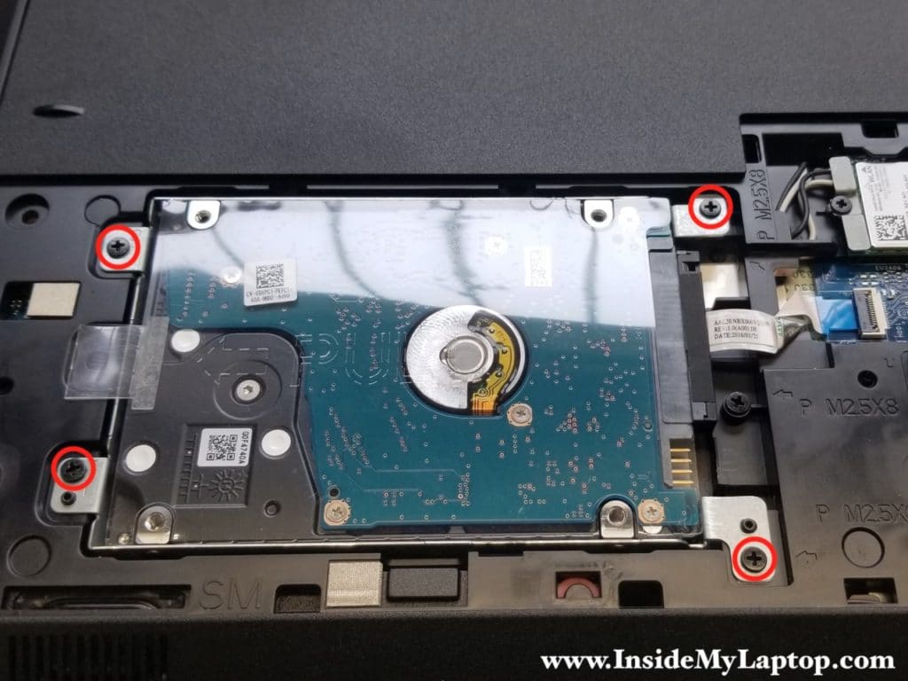
STEP 4.
Remove four screws securing the hard drive bracket.
STEP 5.
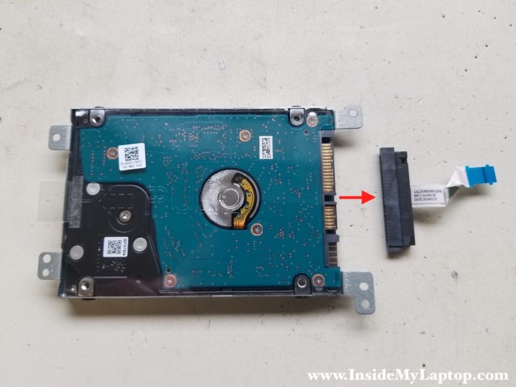
Unlock the connector (red arrow) and disconnect the hard drive SATA cable from the motherboard.

STEP 6.
Unplug the SATA cable from the hard drive.
It’s necessary only if you are replacing or upgrading the hard drive.
Installing a 2.5″ SATA solid state drive instead of the regular hard drive will improve laptop performance significantly.
STEP 7.
Dell Inspiron 15 5000 series 5559/5558/5555 has two memory slots.
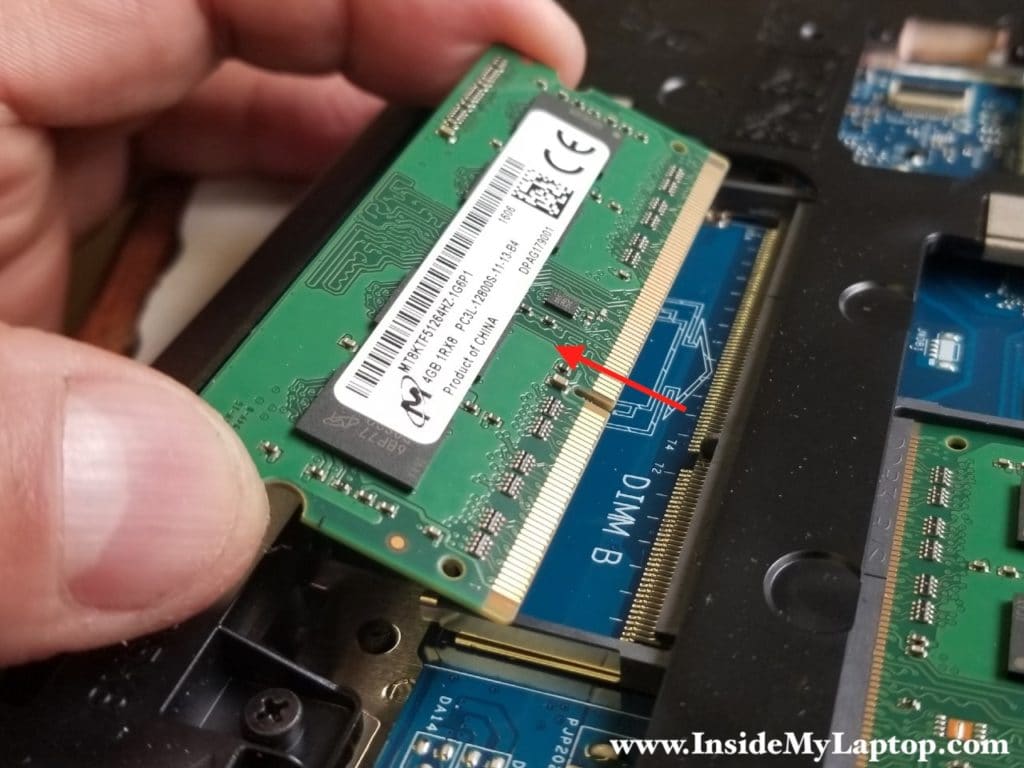
In order to remove the memory module spread latches on both sides of the slot. The memory module will pop up at a 30 degree angle.
This laptop can take up to 16GB (2x8GB) DDR3-12800 SODIMM RAM modules.
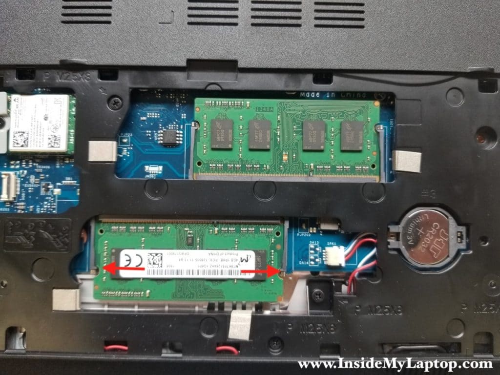
Pull the memory module from the slot.
STEP 8.
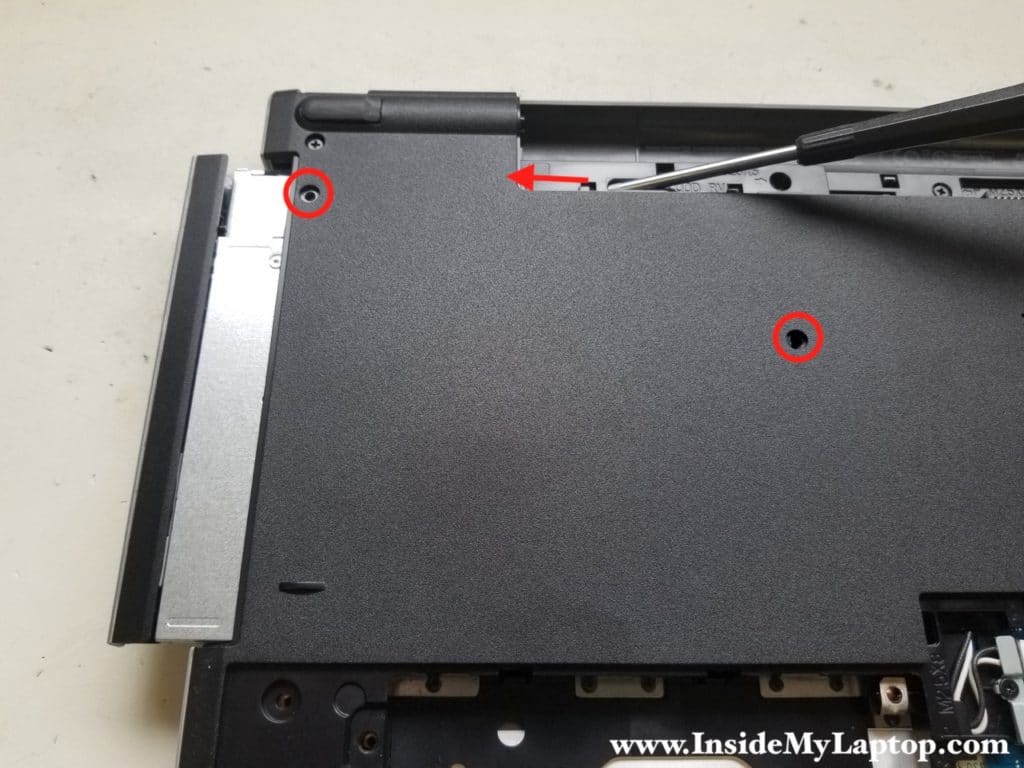
Remove two screws securing the optical drive.
Push the optical drive out through the opening in the battery compartment.
Remove the drive.
STEP 9.
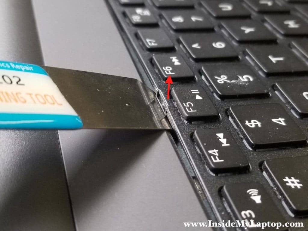
Removing the keyboard from Dell Inspiron 15 5000 series 5559/5558/5555 laptop is a little bit tricky.
There are five hidden latches securing the keyboard.

You’ll need a thin metal case opener to release keyboard latches.
Insert the case opener between the keyboard and the latch.
Push the latch inside.
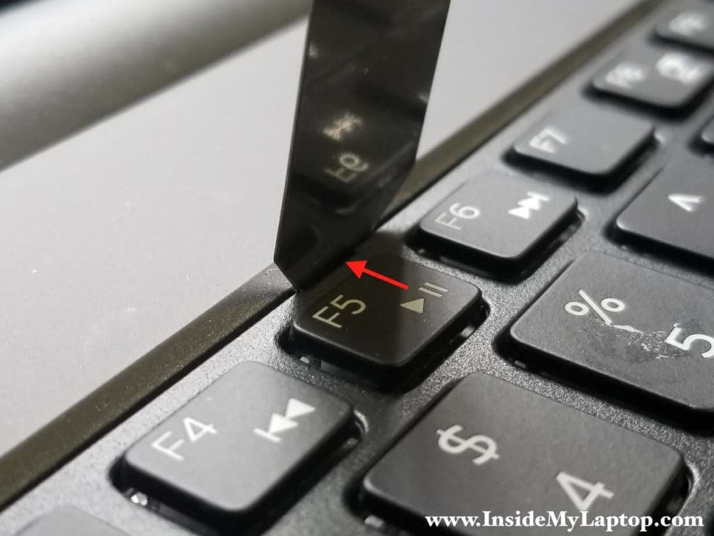
Lift up the keyboard.
Unlock all remaining latches.
STEP 10.
Continue removing the keyboard with your fingers.
You’ll have to apply some reasonable force to separate the keyboard from the top case.
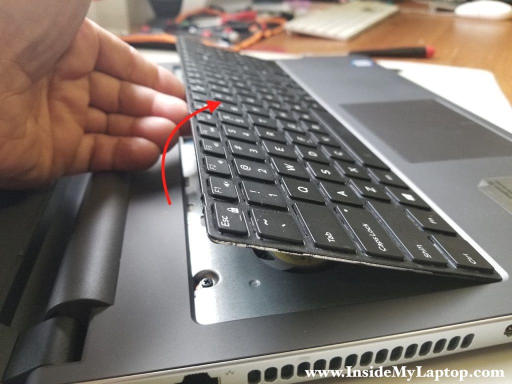
There are small metal knobs securing the keyboard to the top case. They engage with plastic retainers on the back of the keyboard.
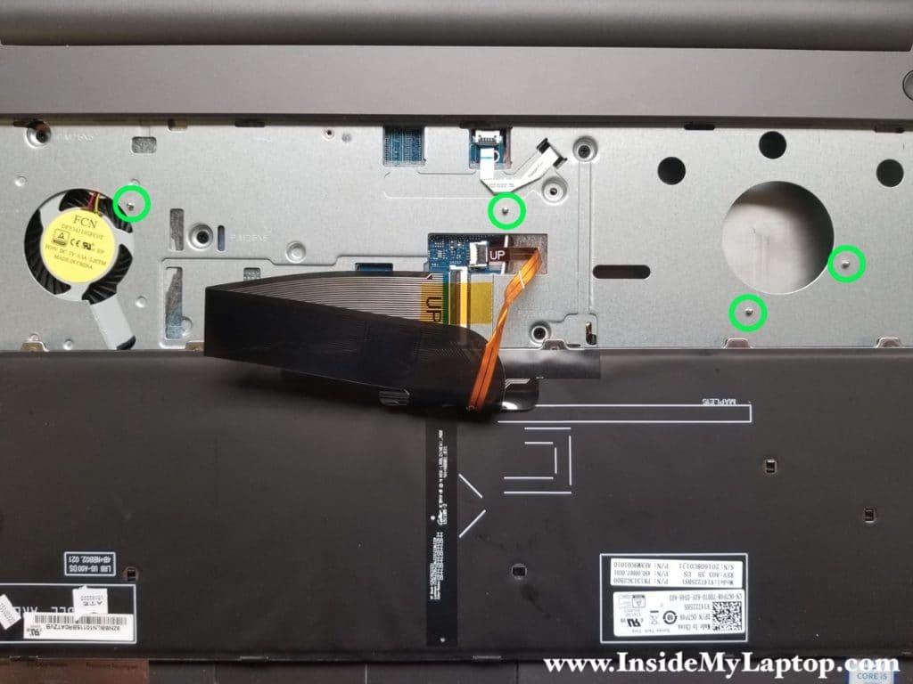
Under the keyboard you will find two flat cables: the keyboard cable and the backlight cable.
Do you see “UP” sign on each cable? Make sure both cables positioned correctly during the reassembly process.
STEP 11.
Unlock the small connector and pull the backlight cable out.
STEP 12.
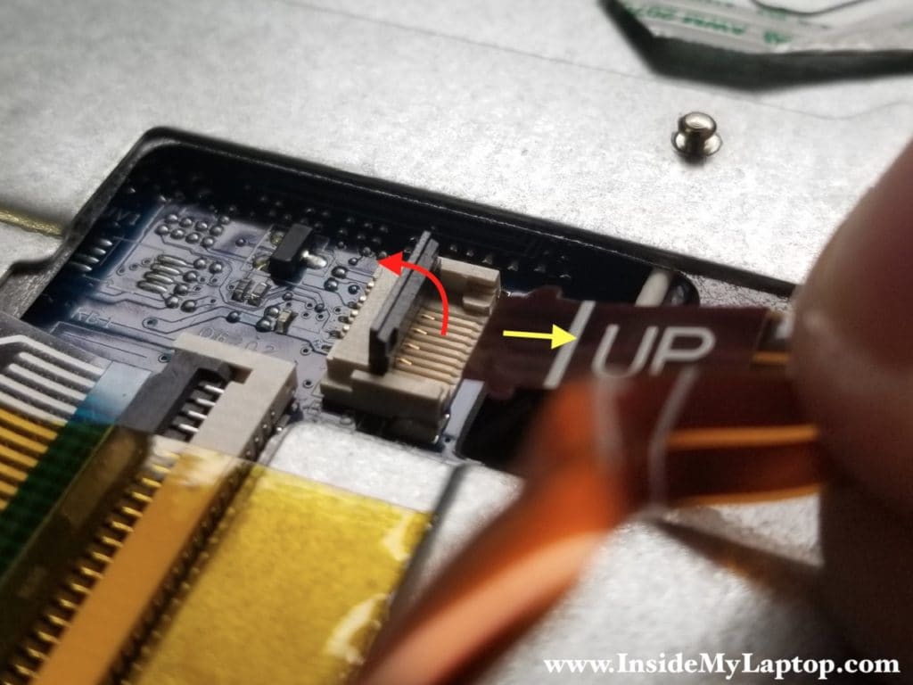
Unlock the big connector and pull the keyboard cable out.
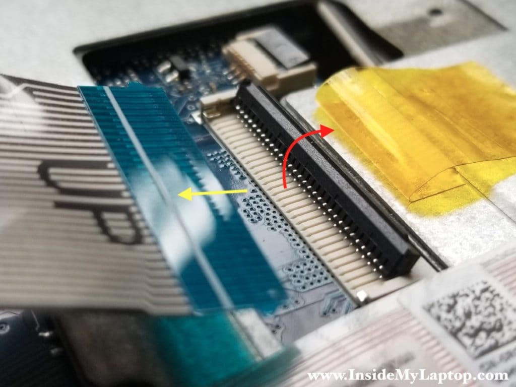
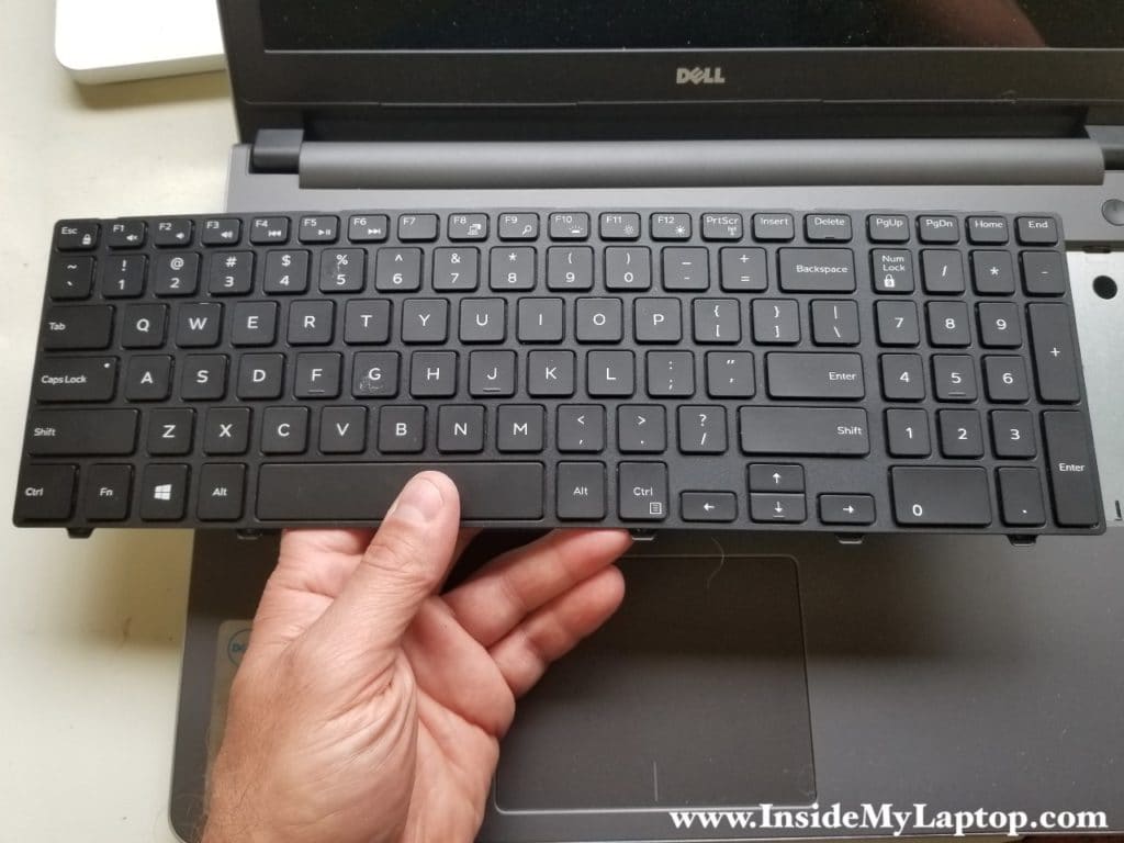
STEP 13.
Remove the keyboard.
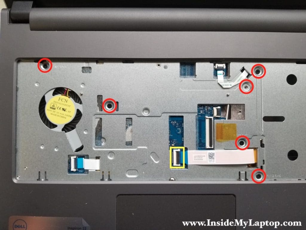
STEP 14.
Remove six screws securing the top case.
Disconnect the optical drive cable from the motherboard.
STEP 15.
Remove all screws from the bottom of the laptop.
Screws I marked in yellow are shorter than screws marked in red.

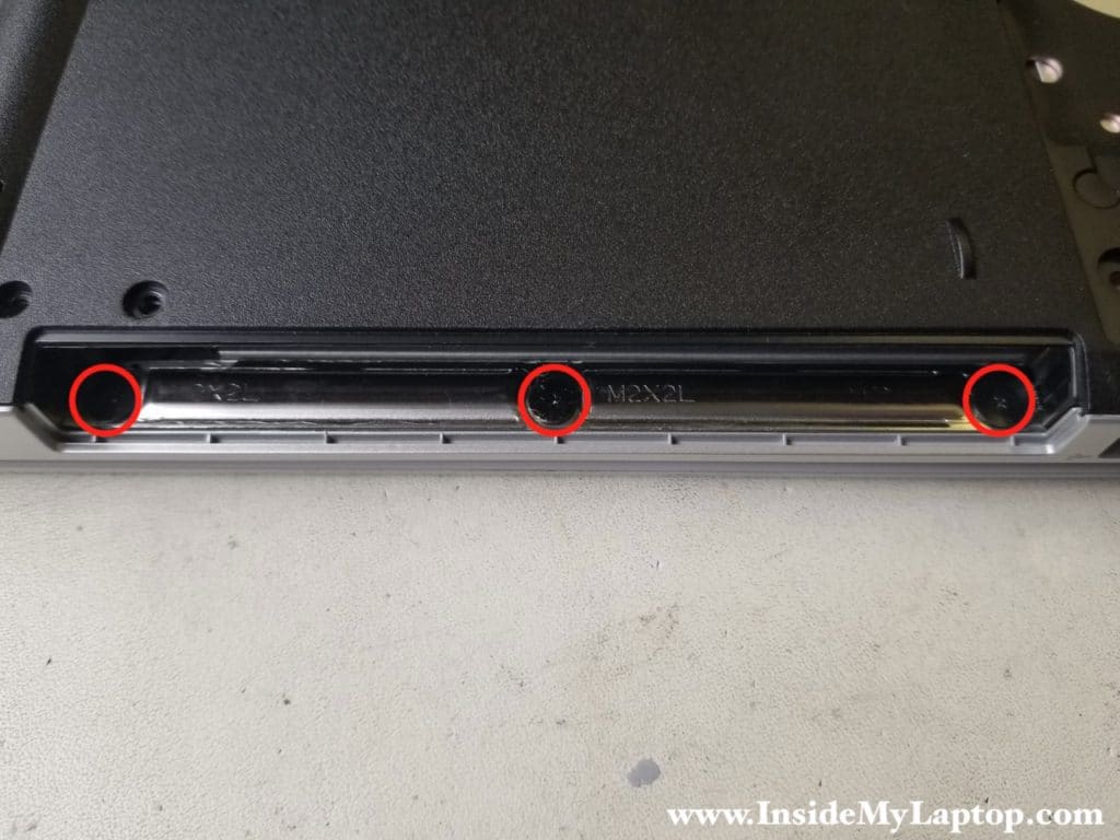
STEP 16.
Remove three more screws located in the optical drive bay.
STEP 17.
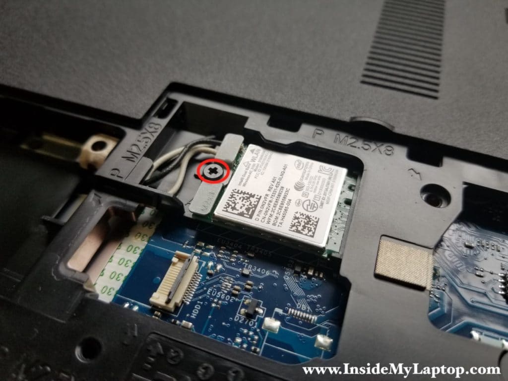
Remove the wireless card bracket which is secured by one screw.
It’s necessary to remove the wireless card if you are going to remove the bottom case.
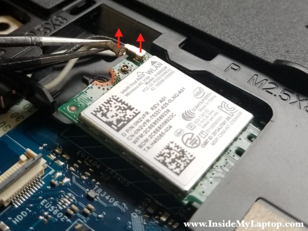
Disconnect both antenna cables from the wireless card.
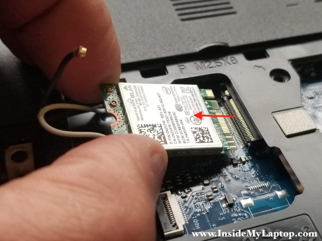
Pull the wireless card out.
STEP 18.
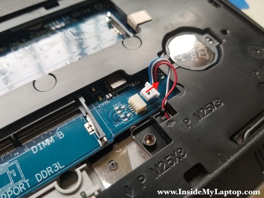
Unplug the speaker cable fro the motherboard.
STEP 19.
Separate the bottom case from the top case using plastic case opener or any other similar tool.
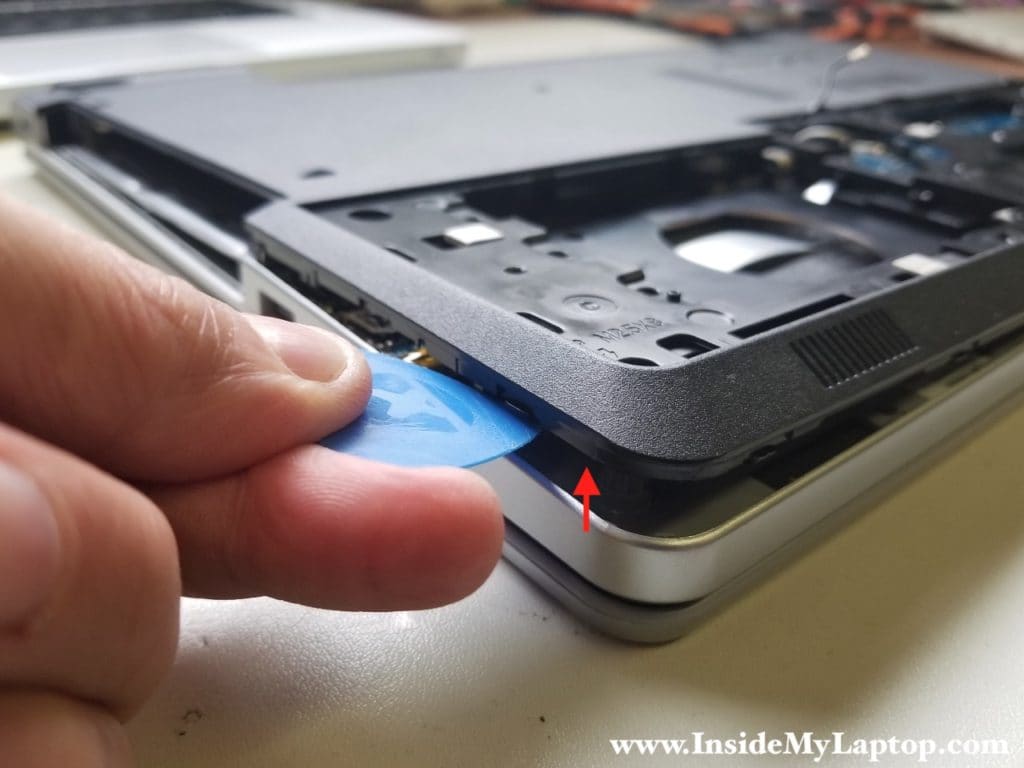
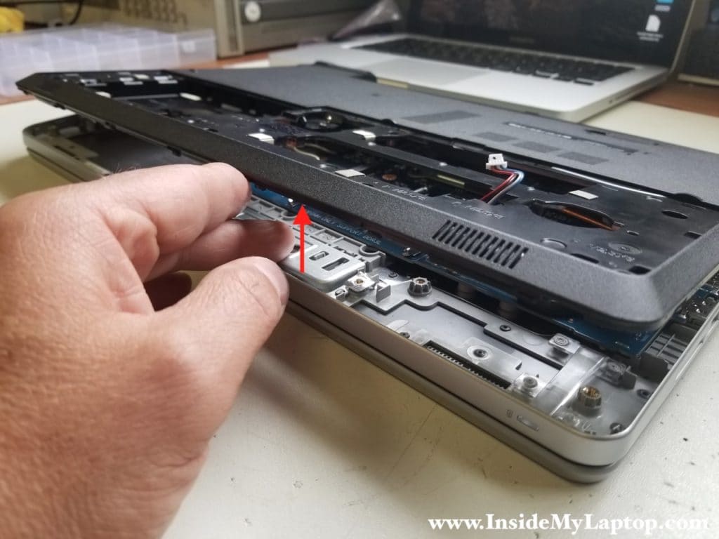
Continue removing the bottom case with your fingers.
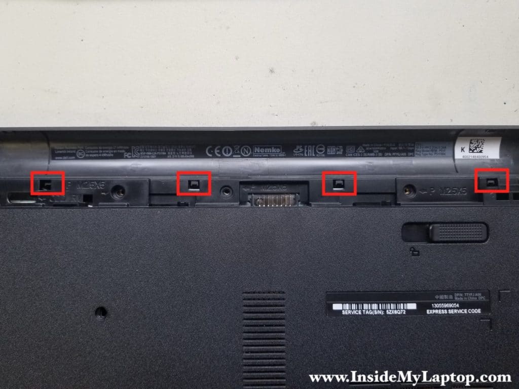
There are four plastic latches securing the bottom case in the battery compartment.
Unlock the latches and continue removing the bottom case.
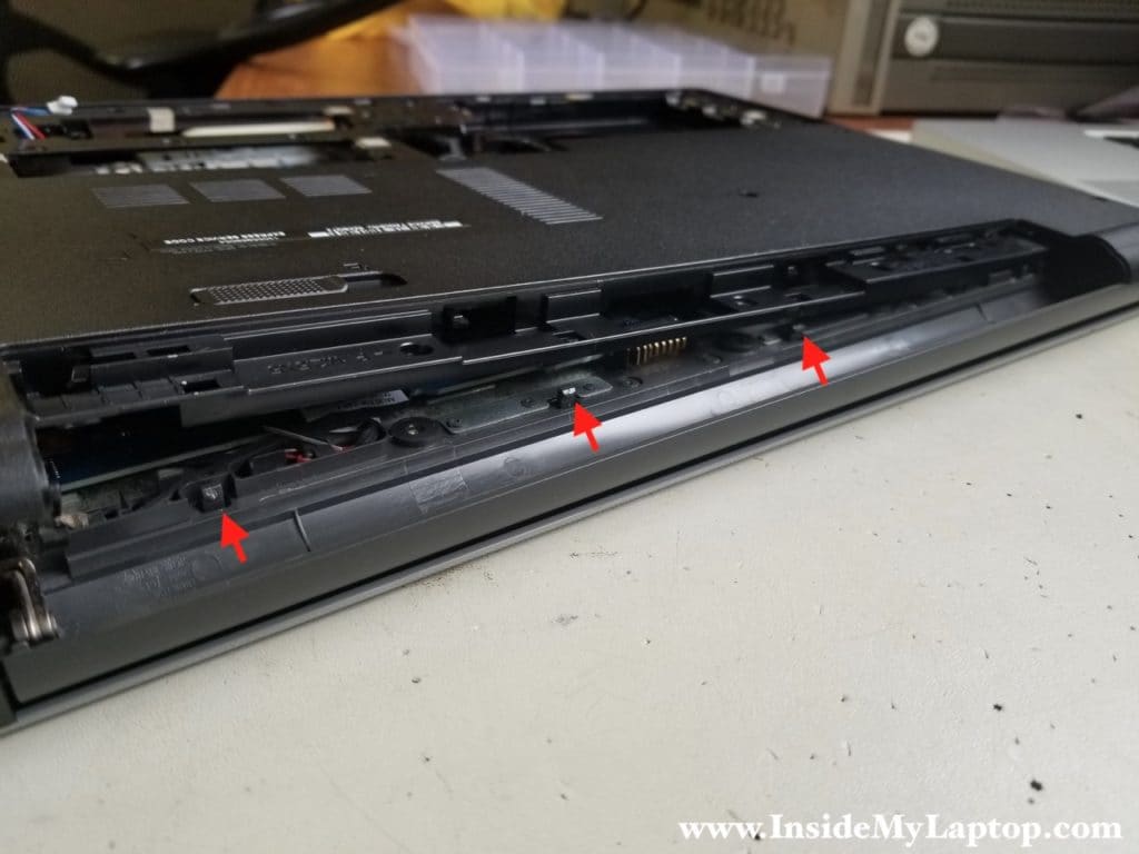
Be careful while removing the bottom case. You’ll have to pull the optical drive cable and Wi-Fi antennas through the openings in the case.

The bottom case has been removed.
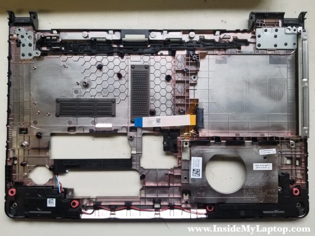
Now you can access most internal components.
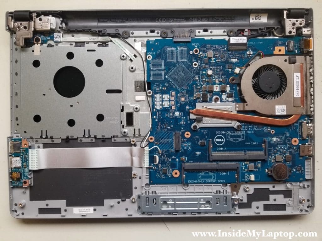
STEP 20.
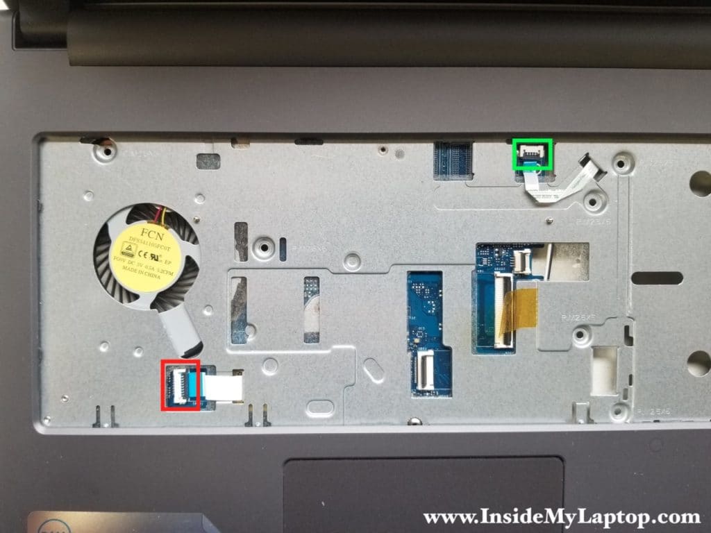
Before removing the motherboard it’s necessary to disconnect two cables on the top case:
- power button cable (green rectangle)
- trackpad cable (red rectangle)
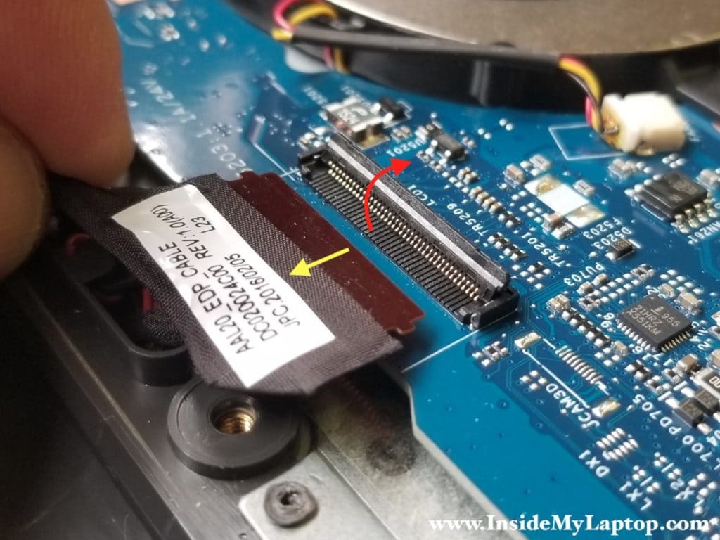
STEP 21.
Unlock the display video cable connector and pull the cable out.
STEP 22.
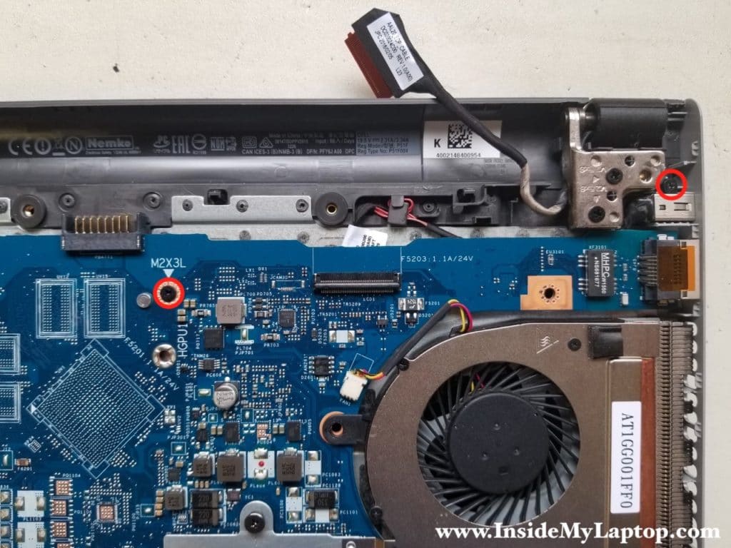
Unroute the display video cable from the guided path.
Remove one screw securing the motherboard.
Remove one screw securing the DC power jack.
STEP 23.
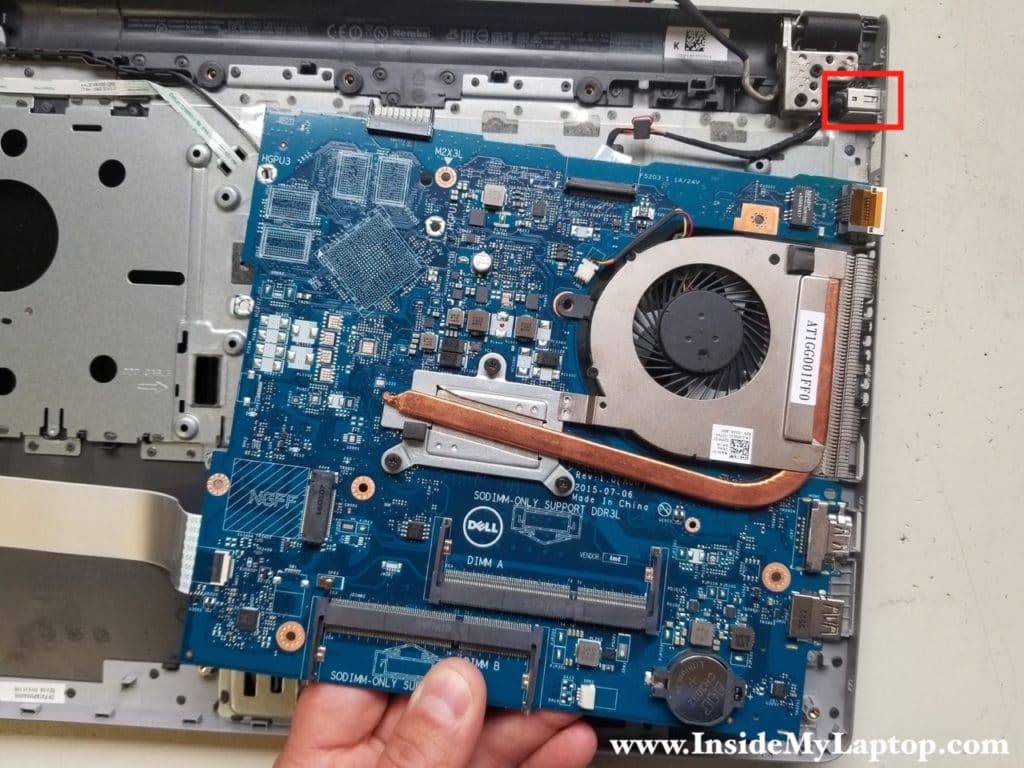
Lift up the motherboard from the bottom case.
NOTE: the DC power jack seated in the case. You’ll have to lift up the DC jack from the case.
STEP 24.
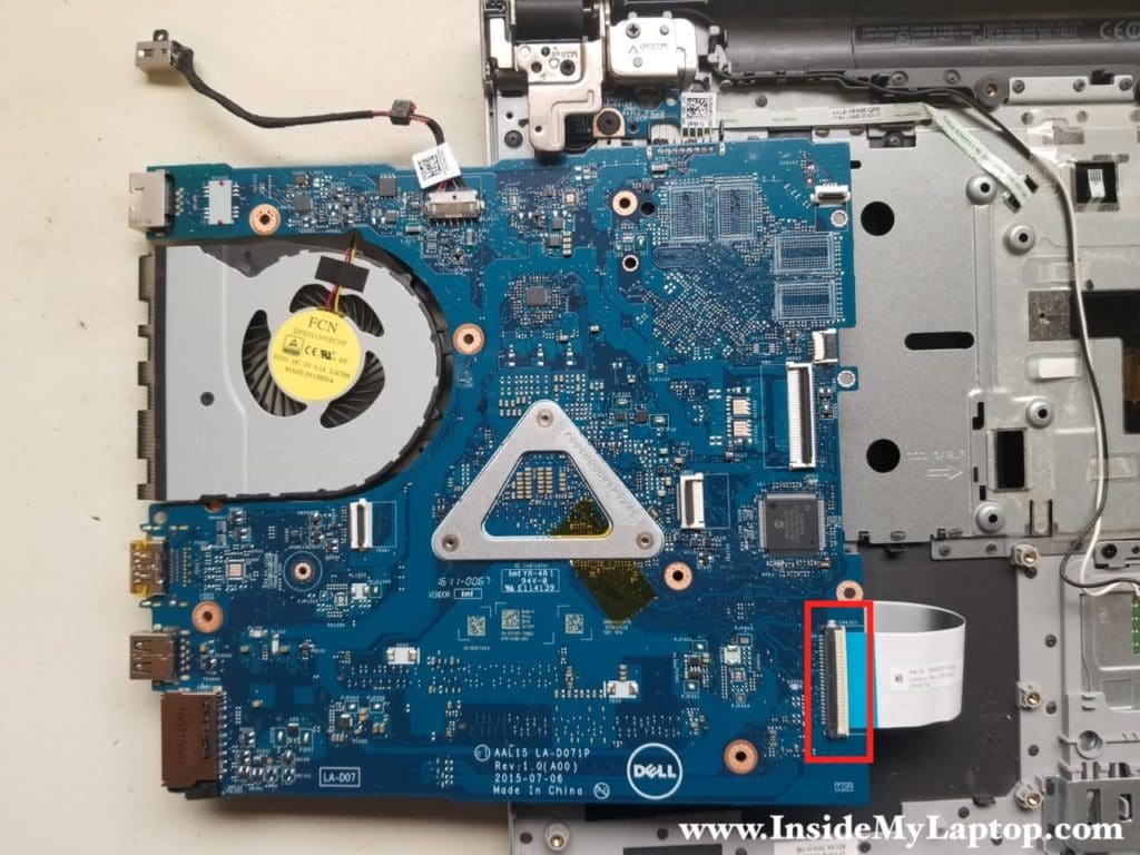
Turn the motherboard upside down and disconnect the USB board cable.
STEP 25.
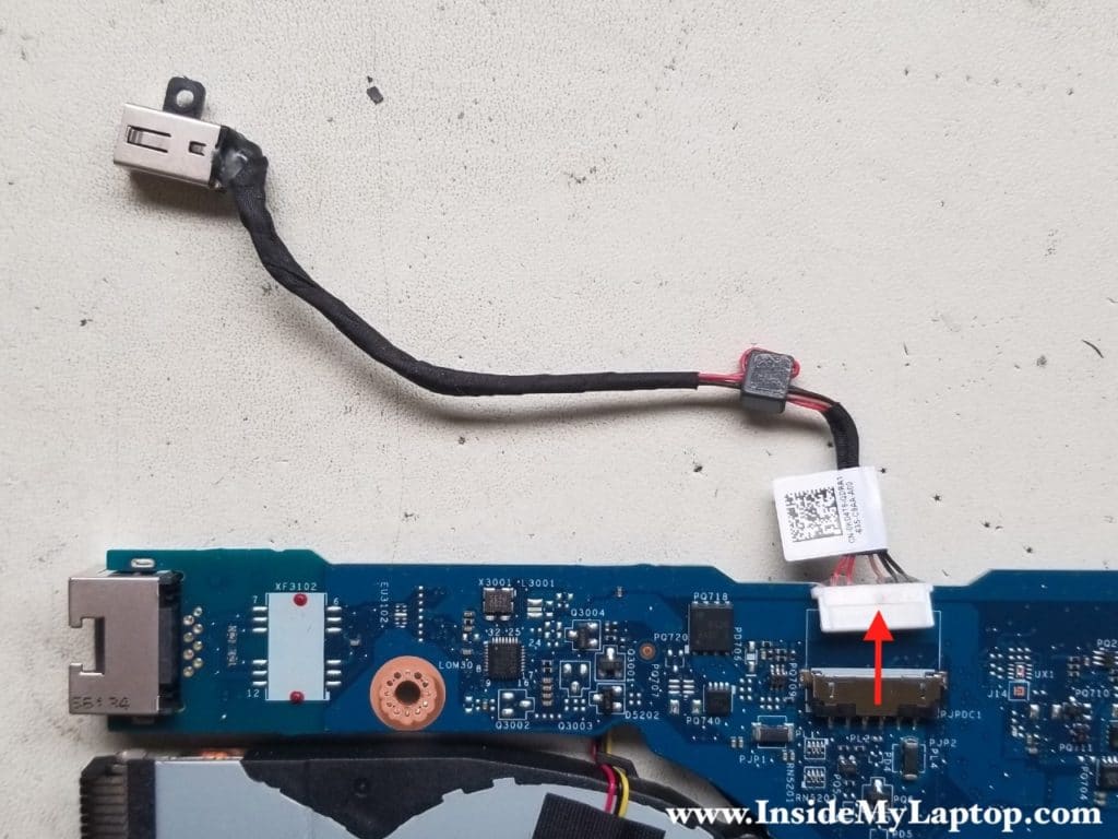
In Dell Inspiron 15 5000 series 5559/5558/5555 laptop the DC jack attached to the power cable.
Disconnect the cable from the motherboard.
STEP 26.
Loosen three screws securing the heatsink.
Disconnect the fan cable from the motherboard.

Separate the heatsink assembly from the motherboard.
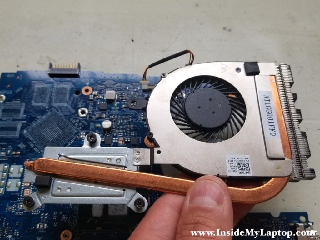
STEP 27.
Remove three screws securing the cooling fan to the heatsink.
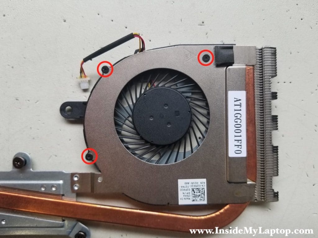
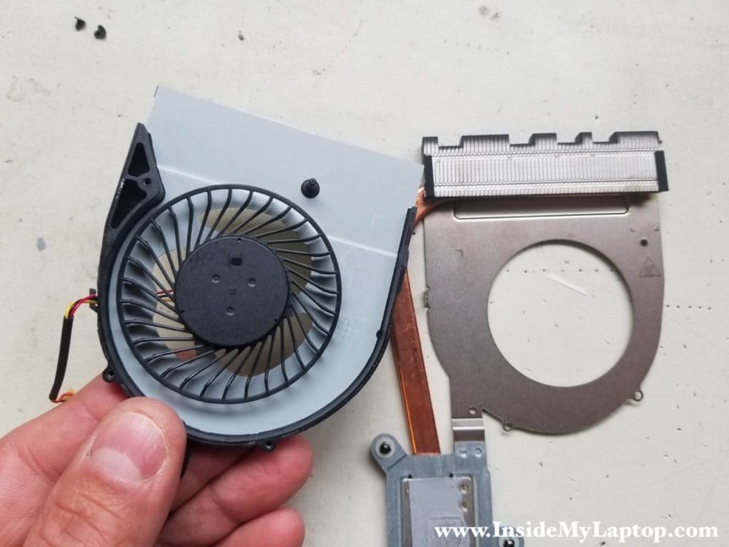
Now you can remove the fan.
15″ and 17″ 5000 series laptops has similar screen removal steps.
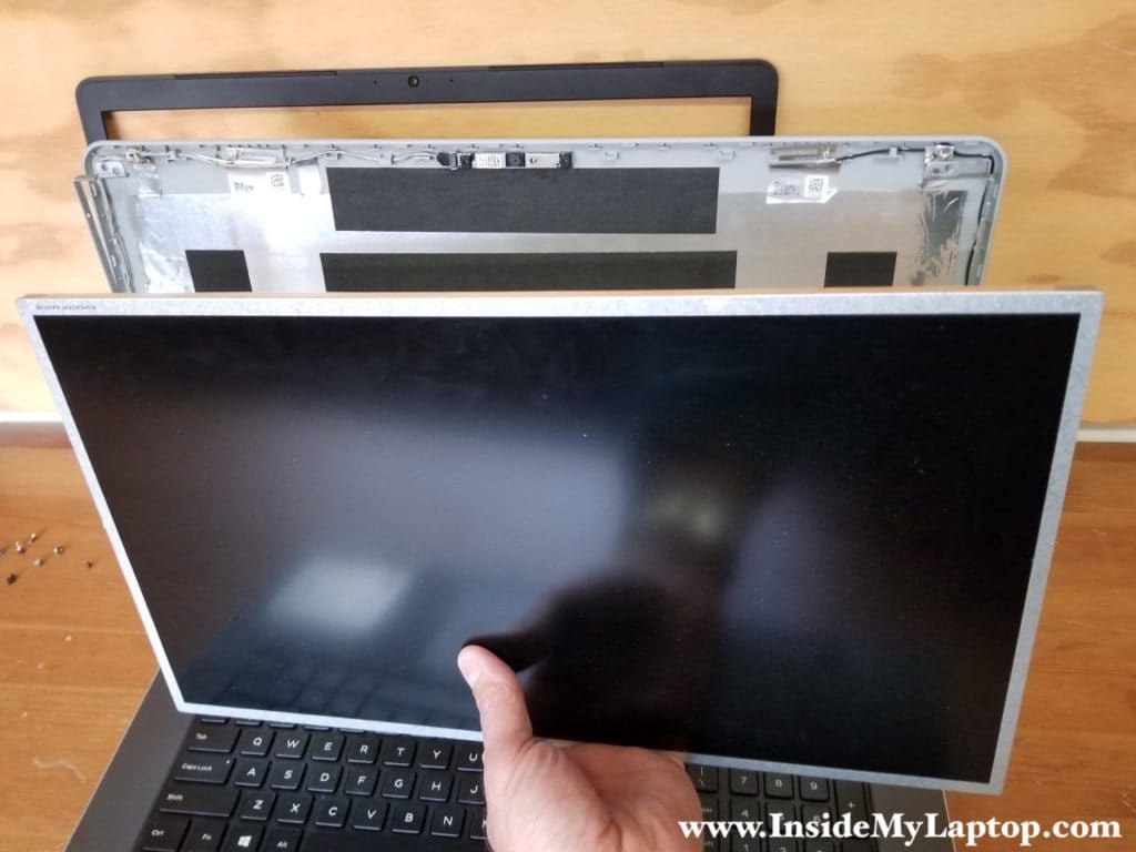
If you need to replace the LCD screen, take a look at the display disassembly guide.
Nikhil
What is the part number for power adapter jack? Can you give detailed snapshots for the power jack? and if possible also mention site on which I can buy that.
IML Tech
@ Nikhil,
You can see the DC jack in the step 25.
Part number: 0KD4T9
Search eBay for this part number.
Mike S.
Will removing the CMOS battery from the motherboard allow me to boot the computer past the boot password?
My laptop had been stolen and I recently recovered it, but as soon as I power it up, it is asking for a password, which of course, I do not know.
Tanyiah
this is so exactly what I needed!!!
sharing knowledge is a powerful tool so keep posting
I will also bookmark this website for future reference.
Tanyiah
Thank you for sharing