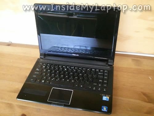
In this guide I will be taking apart an Asus UL80J laptop in order to repair damaged DC power jack.
As you see on the following picture, the DC jack got pushed into the case to the point that the AC adapter will not plug in anymore.
I will disassemble this computer, show why it happened and how to repair the problem without buying any spare parts.
During the disassembly process I’ll go though the following major steps:
STEP 1-5: Accessing both RAM modules. Removing the hard drive and optical drive.
STEP 6-13: Disconnecting and removing the keyboard.
STEP 14-22: Removing the top cover (palm rest) assembly.
STEP 23-24: Removing and disconnecting the cooling fan.
STEP 25-29: Fixing damaged DC jack.
Let’s start.
STEP 1.
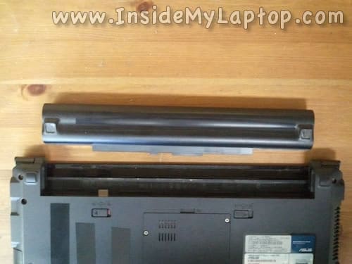
First of all, make sure the computer is turned off.
Unlock and remove the battery.
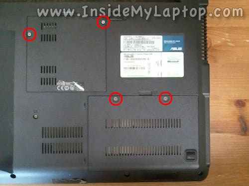
STEP 2.
Remove screws securing the hard drive and RAM (memory) covers.
Remove both covers.
NOTE: it’s not necessary to remove the RAM cover for the purpose of my repair. I’m doing that just to show how to access RAM slots.
STEP 3.
Slide the hard drive to the right to disconnect it from the motherboard.
This laptop can take up to 8GB (2x4GB) DDR3-12800 SODIMM RAM modules.
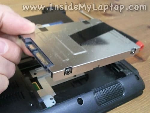
STEP 4.
Lift up and remove the hard drive assembly.
Upgrading this 2.5″ hard drive to a 2.5″ SATA solid state drive will improve laptop performance significantly.
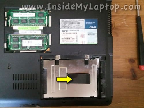
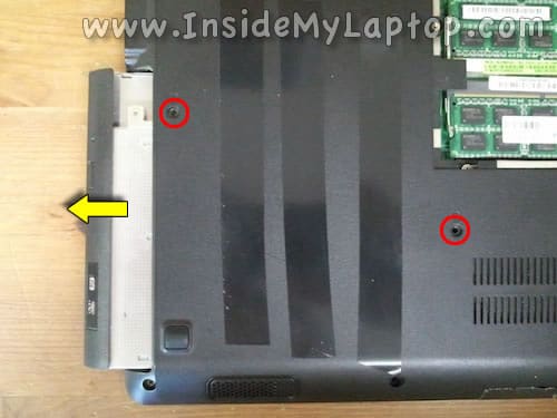
STEP 5.
Remove two screws securing the optical drive.
Slide the optical drive to the left and remove it.
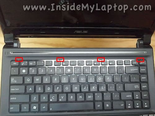
STEP 6.
The keyboard is secured to the case by four tiny latches.
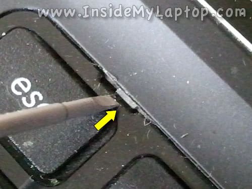
STEP 7.
Push the left latch into the case using a small flat head Phillips screwdriver.
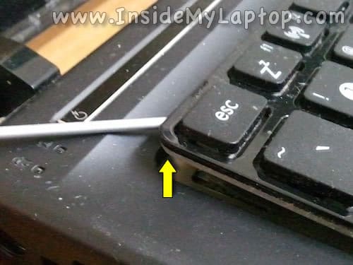
STEP 8.
While the latch is pushed in, lift up the corner of the keyboard so the latch doesn’t lock back.
Unlock all remaining latches.
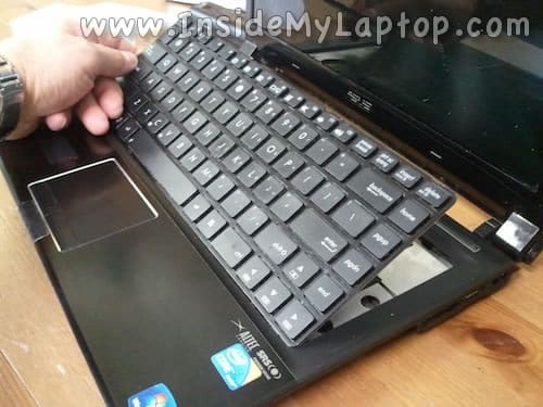
STEP 9.
Now you can separate the upper side of the keyboard from the case.
Turn the keyboard over and place it upside down on the palmrest.
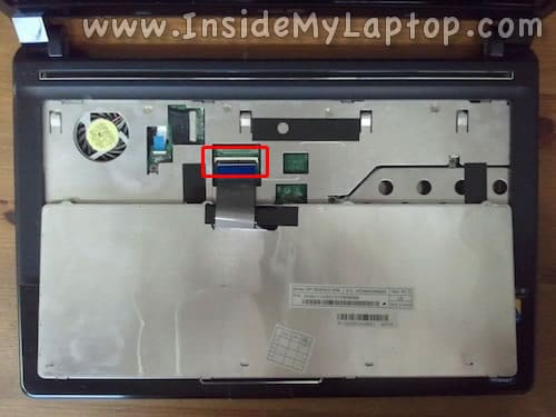
STEP 10.
Now you can access the keyboard cable connector.
STEP 11.
Here’s how to unlock the keyboard connector.
Carefully lift up the left side of the cable retainer with your fingernail.
The retainer will open up at a 90 degree angle.
STEP 12.
After the connector is unlocked, you can pull the cable.
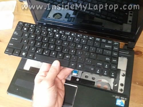
STEP 13.
Remove the keyboard from the laptop.
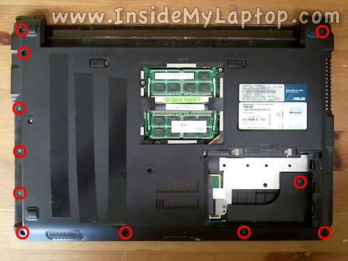
STEP 14.
Remove all shown screws from the bottom.
STEP 15.
Remove screws securing the top cover assembly.
Disconnect two cables.
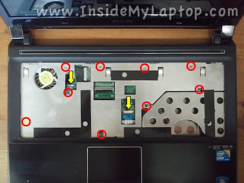
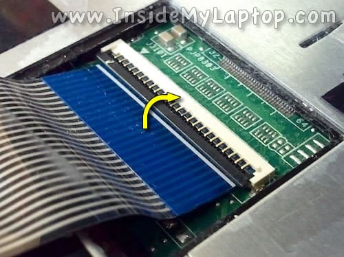
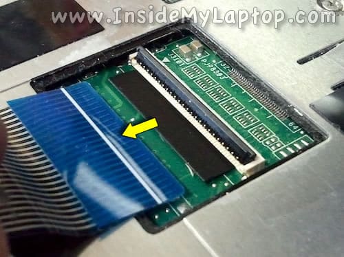
STEP 16.
Here’s how to unlock the connector located closer to the cooling fan.
It’s similar to the keyboard connector shown in steps 11 and 12.
STEP 17.
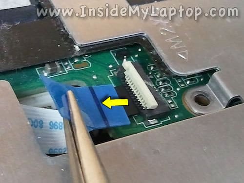
The trackpad connector is a little bit different.
In order to unlock the connector you’ll have to slide the cable retainer about 2-3 millimeters towards the trackpad.
NOTE: the retainer must remain attached to the connector base.
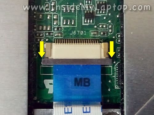
STEP 18.
On the following picture the trackpad connector shown in the unlocked state.
Now you can pull the cable from the connector.
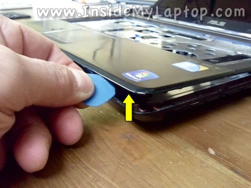
STEP 19.
Start separating the top cover assembly from the base using a guitar pick (or any other piece of plastic).
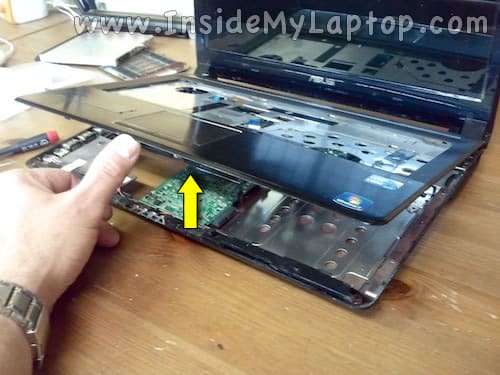
STEP 20.
Continue separating the top cover assembly from the bottom.
STEP 21.
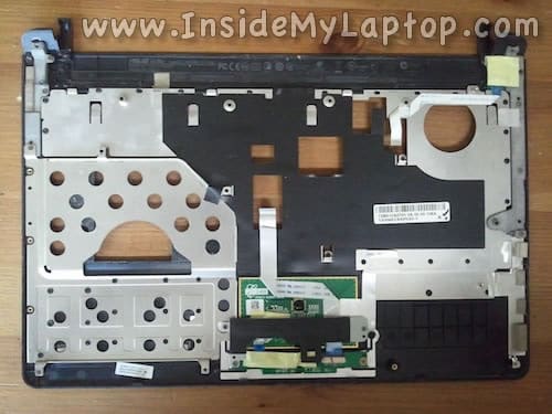
The top cover (palm rest assembly) has been removed.

Here’s a picture of the bottom side of the top cover assembly.
STEP 22.
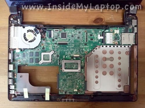
After the top cover removed, you can access all internal components.
In the following two steps I’ll show how to remove the cooling fan. It’s not necessary for the purpose of my repair but the fan looks dirty and I’ll clean it up.
STEP 23.
Remove two screws securing the cooling fan.
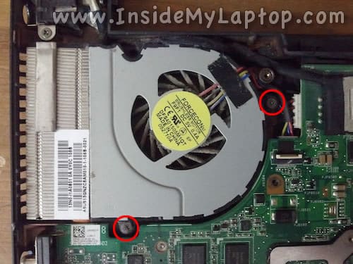
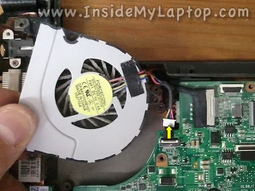
STEP 24.
Lift up the cooling fan and disconnect the cable.
Now you can clean up the fan and heat sink if they are dusty.
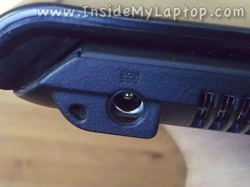
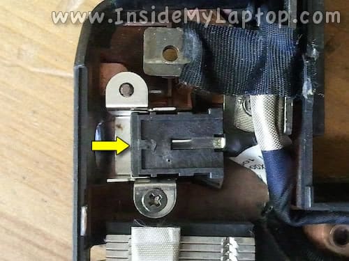
STEP 25.
Finally, let’s take a look at the DC jack.
As you see, the DC jack dislocated from its normal position.
The left side of the jack should almost touch the case but it’s located about 5-6 millimeters away from the case.
Remove one screw securing the metal bracket to the case and remove the DC jack with the bracket.
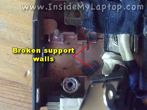
STEP 26.
Now you can see why the DC jack got dislocated.
The jack had support walls behind and they are broken.
Apparently, the laptop was dropped while being plugged into the AC adapter and landed on the power plug.
Remove all broken and loose plastic pieces.
STEP 27.
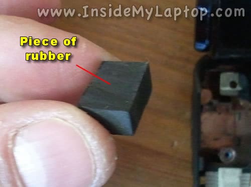
Instead of replacing the entire bottom cover I’ll do some modification to the DC jack.
I’ll use a piece of rubber as a support wall for the DC jack. Probably a regular pen eraser will work just fine for that.
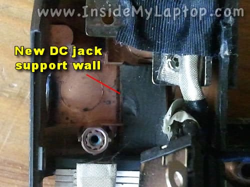
STEP 28.
Install the rubber piece so it fits behind the jack.
Make sure the rubber piece has correct heights and the DC jack seats properly.
After it fitted, you can glue the rubber piece to the bottom case.
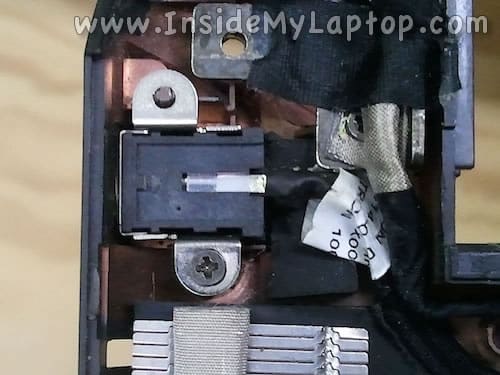
STEP 29.
Install the DC jack back in place and make sure it’s secured.
As you see, the rubber piece fitted very tightly behind the jack and supports it very well.
Angel
WOW!!! Congrats on being the ONLY website that I found with a complete disassembly guide for my UL80JT…I’ve been looking for MONTHS. Why you ask? My computer detects two unused ram slots….I know where the ram slots are on the underside…but do not see the other two…perhaps you can shed some light on this?
P.S.-I’m not afraid to break my baby down to install more ram….got 8GB now…if there are two more slots…I’m ready to get to them 😉
Many many thanx!!!!
Angel
IML Tech
@ Angel,
According to Crucial website UL80JT has only 2 memory slots. Taking it apart will not help. 🙂 There are no additional memory slots inside, only those you can find on the bottom.
Helena
Am looking forward to taking my old and battered laptop to pieces tomorrow to try and mend it. Even though it is a different model I think your steps will work. Thank you
IML Tech
@ Helena,
In general, all laptop disassembly steps are very similar. If you know how to take apart one or two models, you know how to take apart most of them. 🙂
I hope it works well for you. Good luck!