In this guide I show how to disassemble a Lenovo ThinkPad E490 or E495 laptop. All disassembly steps should work for machine types 20N8, 20N9, 20NE and 20NG.
I’ll start this disassembly process with the keyboard removal because it can be done without removing any other part. After that I’ll show how to remove the base cover and access all internal components.
During the disassembly I was using the following repair tools: Phillips screwdriver #1 and #0, thin metal case opener, plastic spudger tool and tweezers.
At the end of this guide I will attach a link to the official Lenovo ThinkPad E490 and E495 hardware maintenance manual. If you need more detailed disassembly instructions, please refer to the service manual.
Keyboard removal
The keyboard removal part is a little bit tricky so pay attention to all the following disassembly steps.
STEP 1.
Insert a thin case opener tool under the left trackpad button.

STEP 2.
Carefully pry up the button and un-snap it from the mounting bracket.
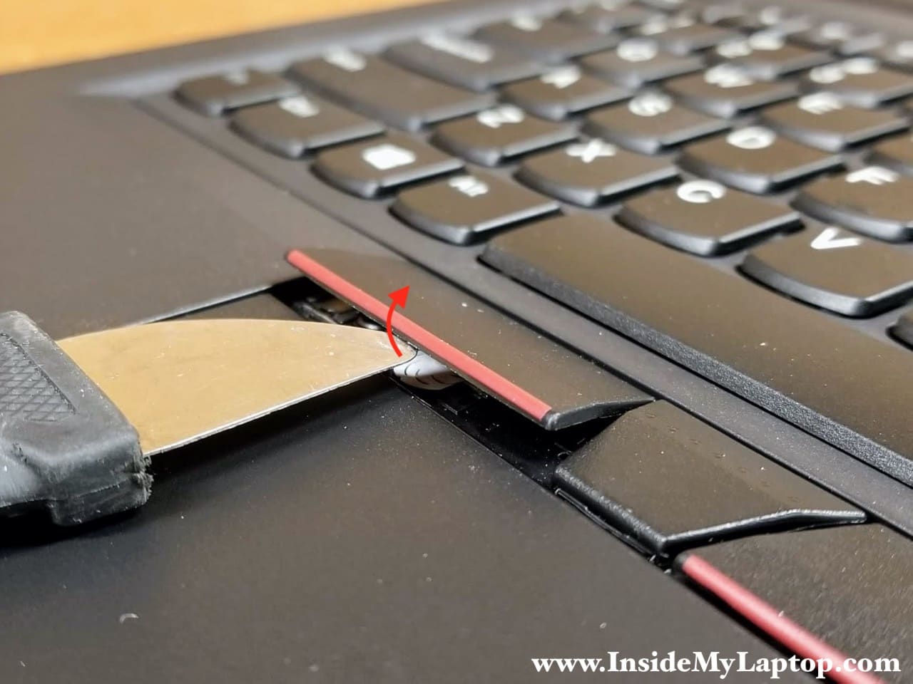
STEP 3.
Remove the left trackpad button and after that remove the right trackpad button the same way.

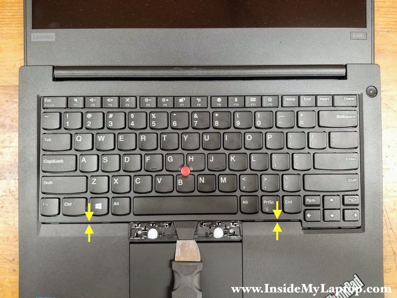
STEP 4.
Loosen two captive screws securing the keyboard to the bezel assembly. Both screws will stay attached to the keyboard when it’s removed.
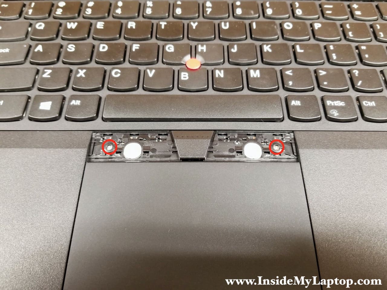
In order to remove the keyboard it’s necessary to slide it towards the display but there are two T-shaped knobs securing the keyboard in place.
On this picture you can see only the left T-shaped knob but there is another one on the right side.

STEP 5.
Insert the case opener tool under the middle button to elevate the keyboard frame above the two T-shaped knobs (located close to screws).

STEP 6.
With the case opener located under the frame slide the keyboard towards the display. The upper side of the keyboard will move under the bezel.
Use both hands to slide the keyboard under the bezel. Shift the keyboard in a short, quick motion.
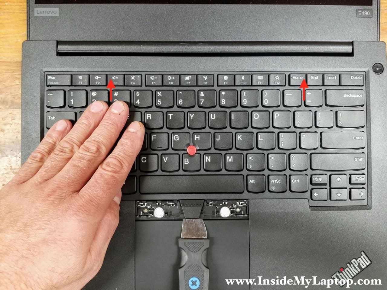
You know you’ve done it properly when you see the top row keys touching the bezel and about 1/8″ gap on the bottom.
STEP 7.
Lift up the lower side of the keyboard and pull it towards the trackpad. Now you can turn the keyboard upside down and place it on the palmrest.

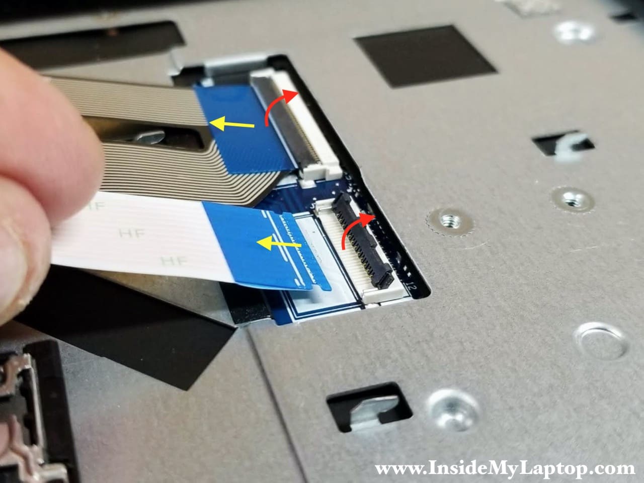
STEP 8.
Disconnect two cables found under the keyboard.
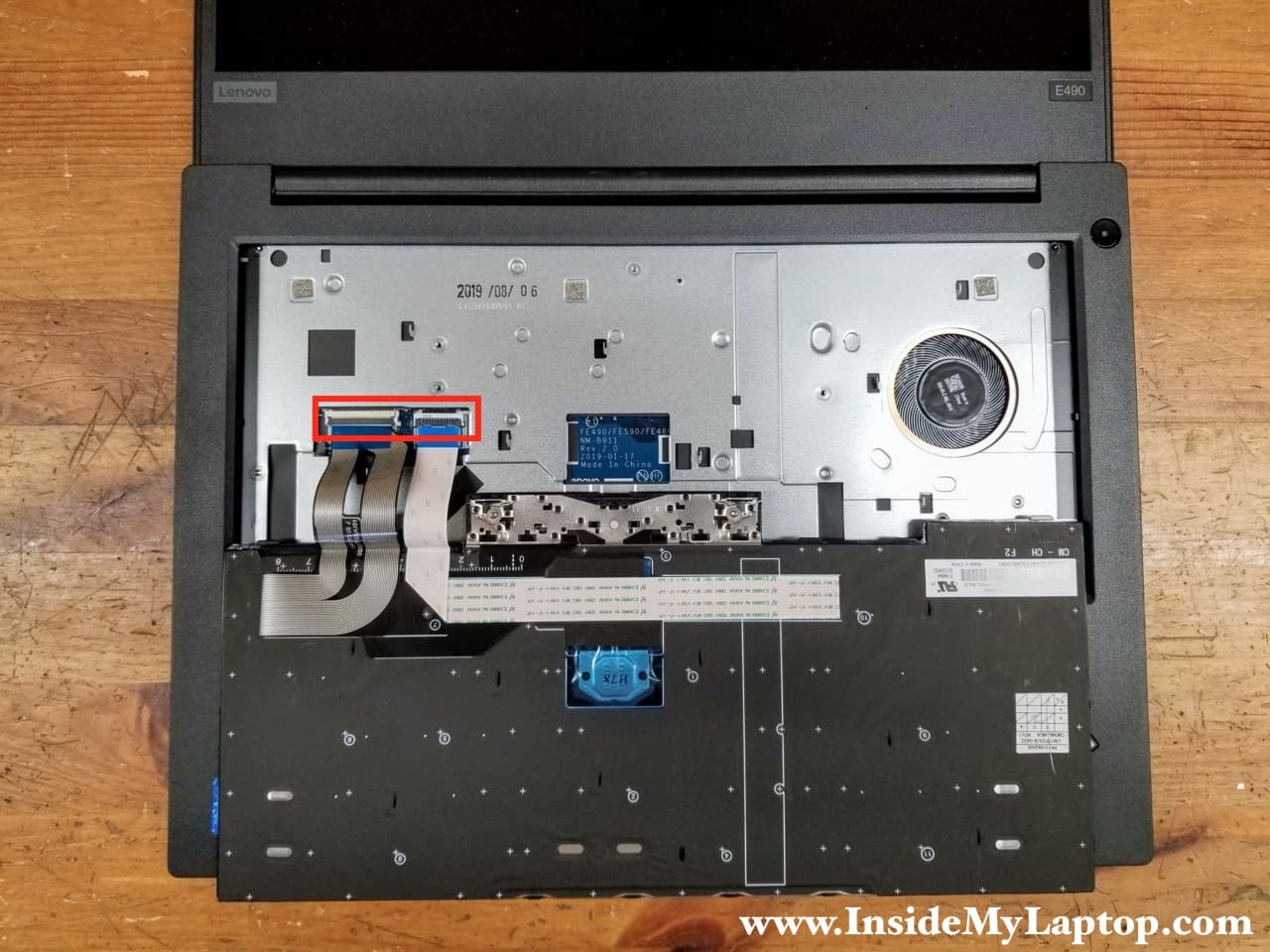
In order to release the cable it is necessary to unlock the connector first.
Lift up the locking tab to unlock the connector and after that pull the cable out.
STEP 9.
Remove the keyboard completely.
Lenovo ThinkPad E490 E495 keyboard FRU part number (English): 01YP240.

Base cover and battery removal
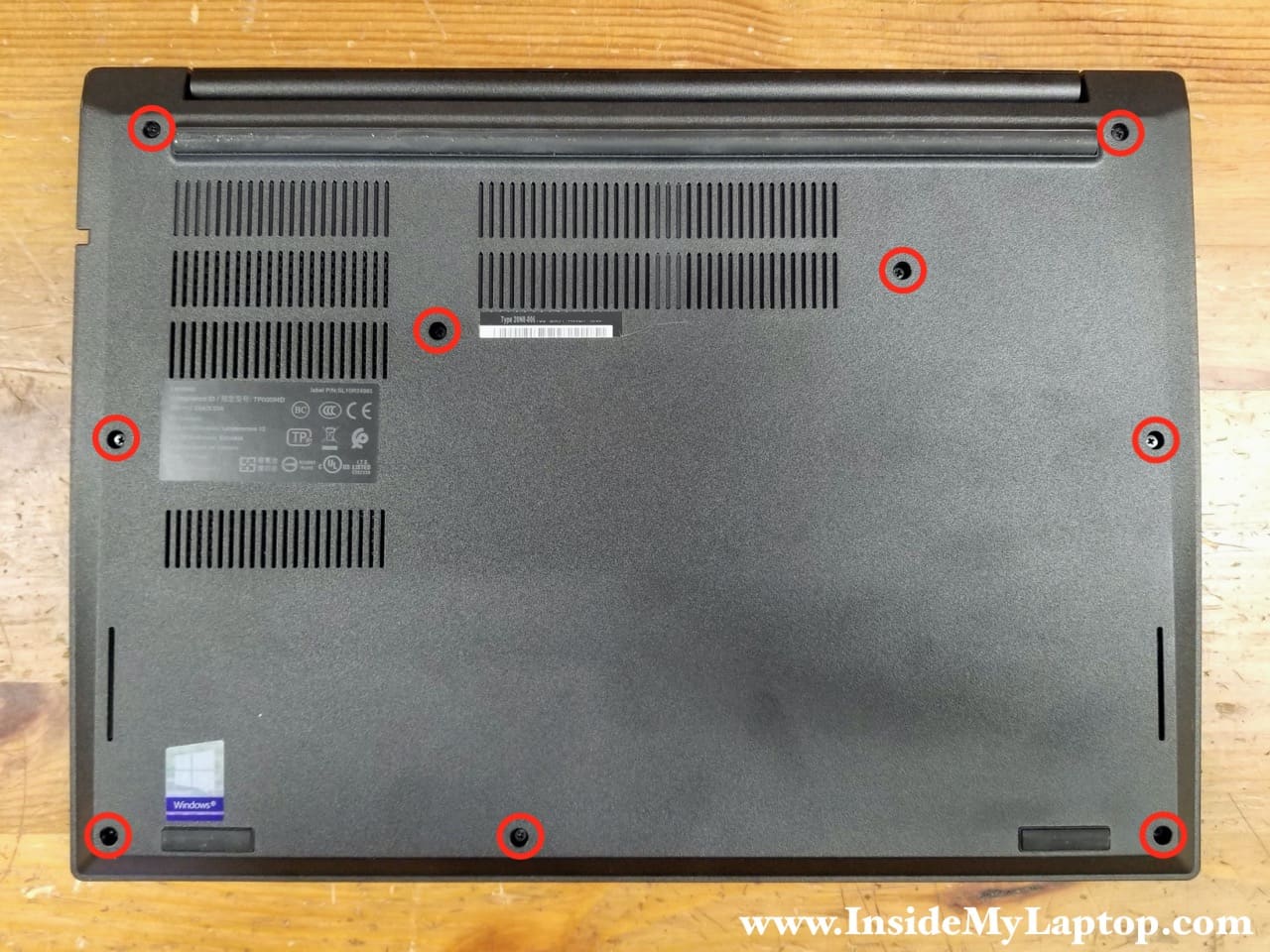
STEP 10.
Loosen nine captive screws securing the base cover.
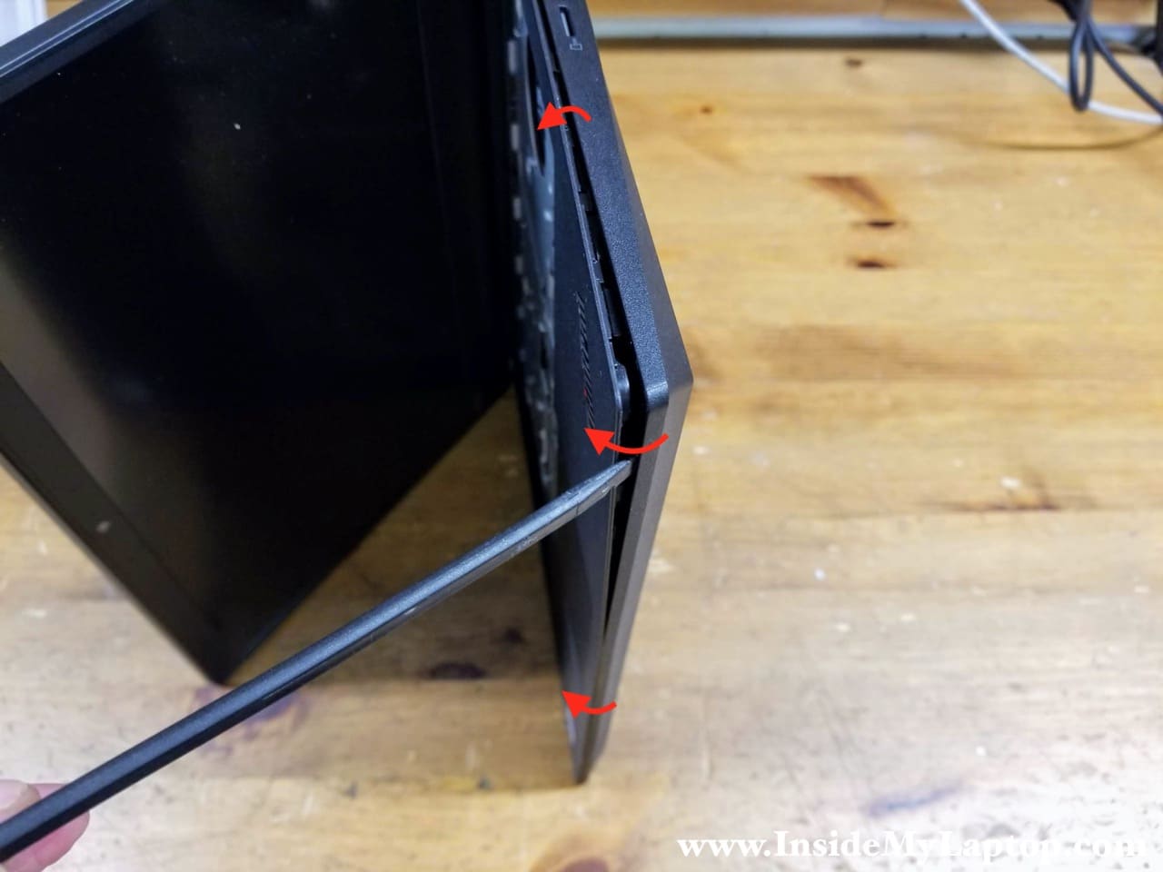
STEP 11.
Place the laptop on its side and start separating the top case from the base cover. I’m using a plastic spudger tool for that.
Move the spugdger along the side and pry up the top case to unlock hidden latches securing it to the base cover.
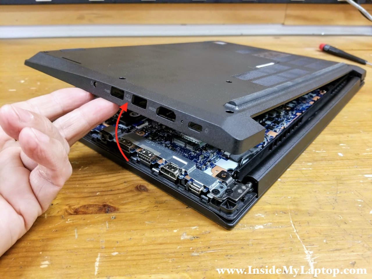
STEP 12.
Continue removing the base cover with your hands.
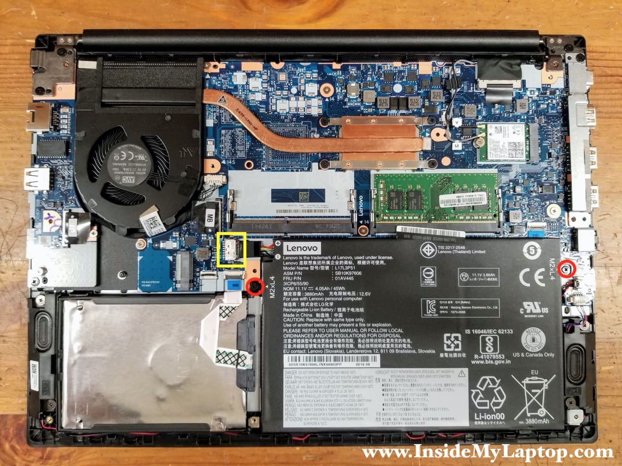
STEP 13.
Remove two screws attaching the battery to the top case. Disconnect the battery cable.
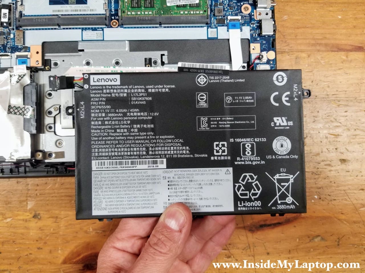
STEP 14.
Lift up and remove the battery.
Lenovo ThinkPad E490 E495 battery model name: L17L3P51.
Memory and hard drive removal
There are two memory slots on the motherboard. You can upgrade memory to 32GB max (2x16GB).
STEP 15.
Remove the memory module.

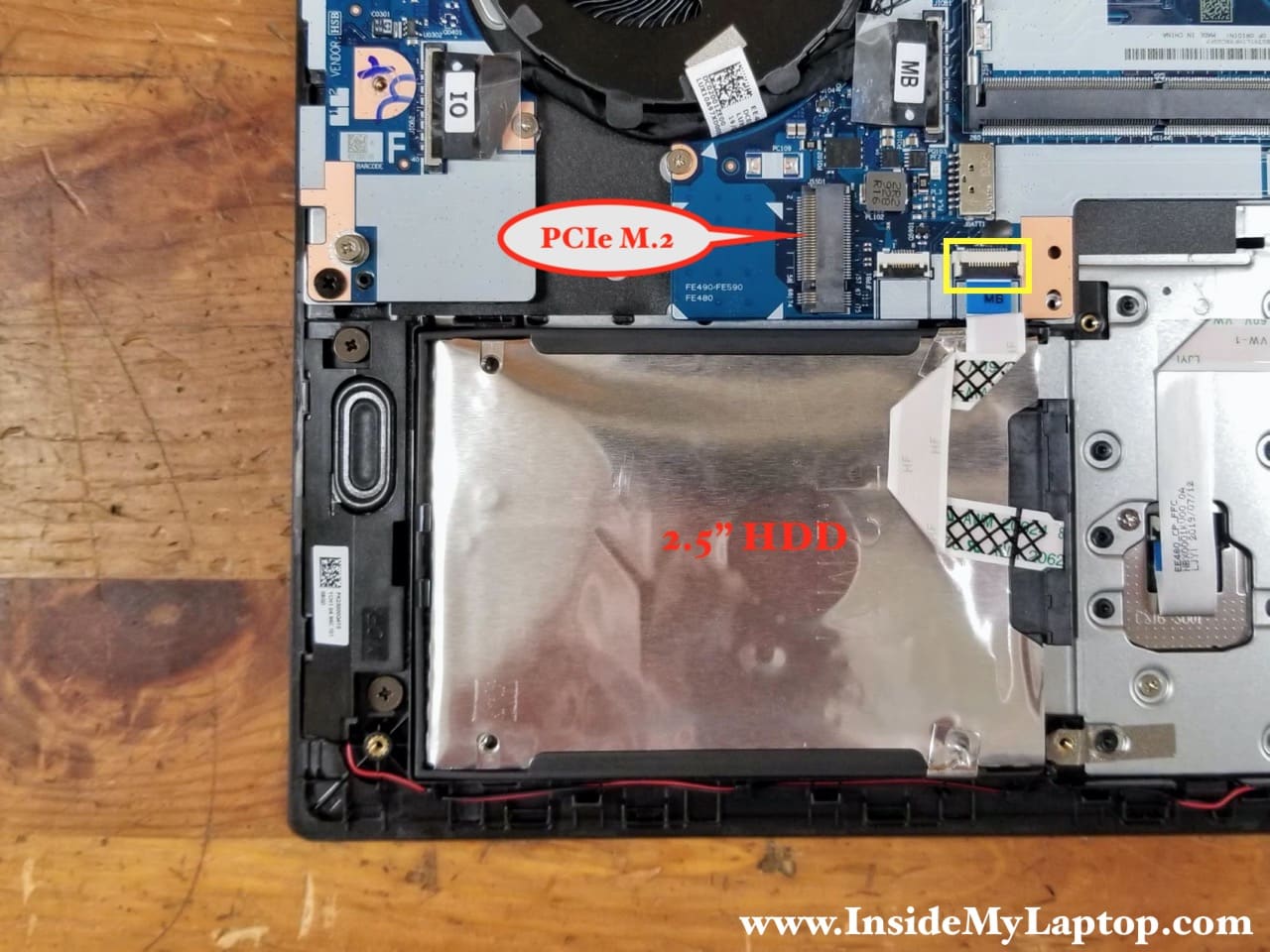
In this particular case the laptop had a regular 2.5″ spinning SATA hard drive installed. The PCIe M.2 slot is available for a PCIe NVMe M.2 SSD upgrade.
STEP 16.
Disconnect the 2.5″ HDD SATA cable from the motherboard.
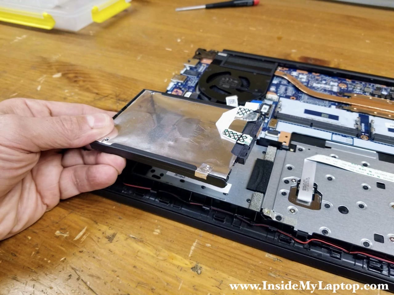
STEP 17.
Pry up the back side of the hard drive and separate it from the top case. There is a small knob securing the hard drive bracket to the case.

STEP 18.
Remove the hard drive with the cable attached to it. You can upgrade this drive to a 2.5″ solid state drive.
Fan and heatsink removal
STEP 19.
Loosen four captive screws securing the fan and heatsink assembly to the motherboard. Disconnect the fan cable.

STEP 20.
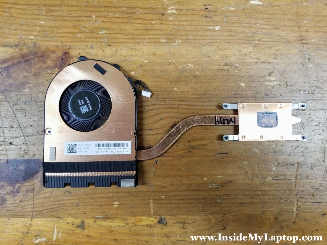
Lift up and remove the fan/heatsink assembly.

Here’s the other side of the fan/heatsink assembly.
Lenovo FRU part number: 02DL824.
Display panel removal
STEP 21.
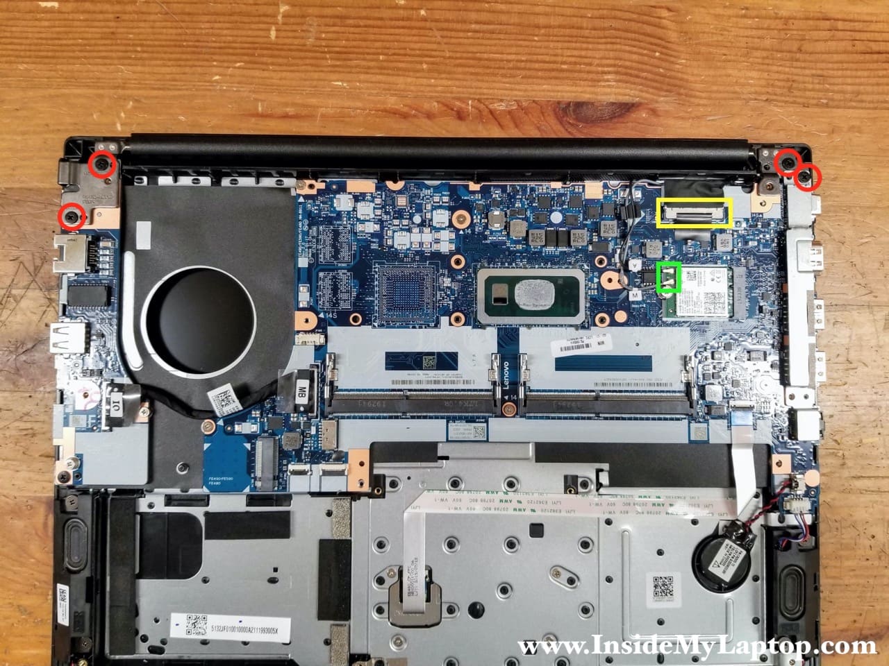
Remove four screws securing the display panel hinges.
Disconnect the display cable (yellow) from the motherboard and two antenna cables (green) from the wireless card.
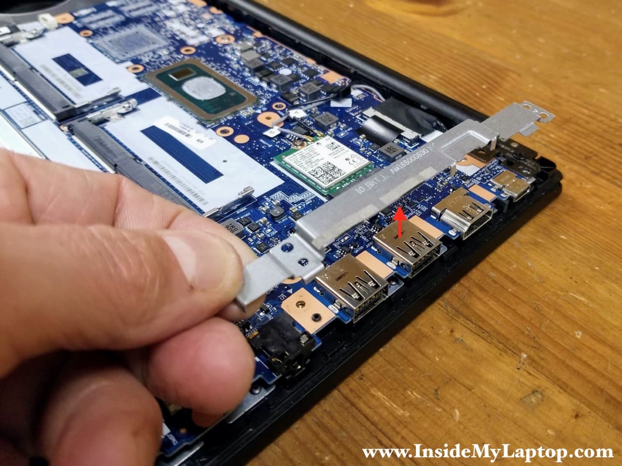
STEP 22.
Lift up and remove the I/O board bracket.
Here’s how to disconnect antenna cable from the wireless card. Simply lift up and un-snap the antenna head from the connector on the wireless card.

The display cable connector has a black tab on top. Pull the display cable connector up to unplug it from the motherboard.

STEP 23.
Lift up the right display hinge as it shown on the picture.

STEP 24.
Lift up the left display hinge.

STEP 25.
Lift up the top case assembly and slide it from under the display hinges.

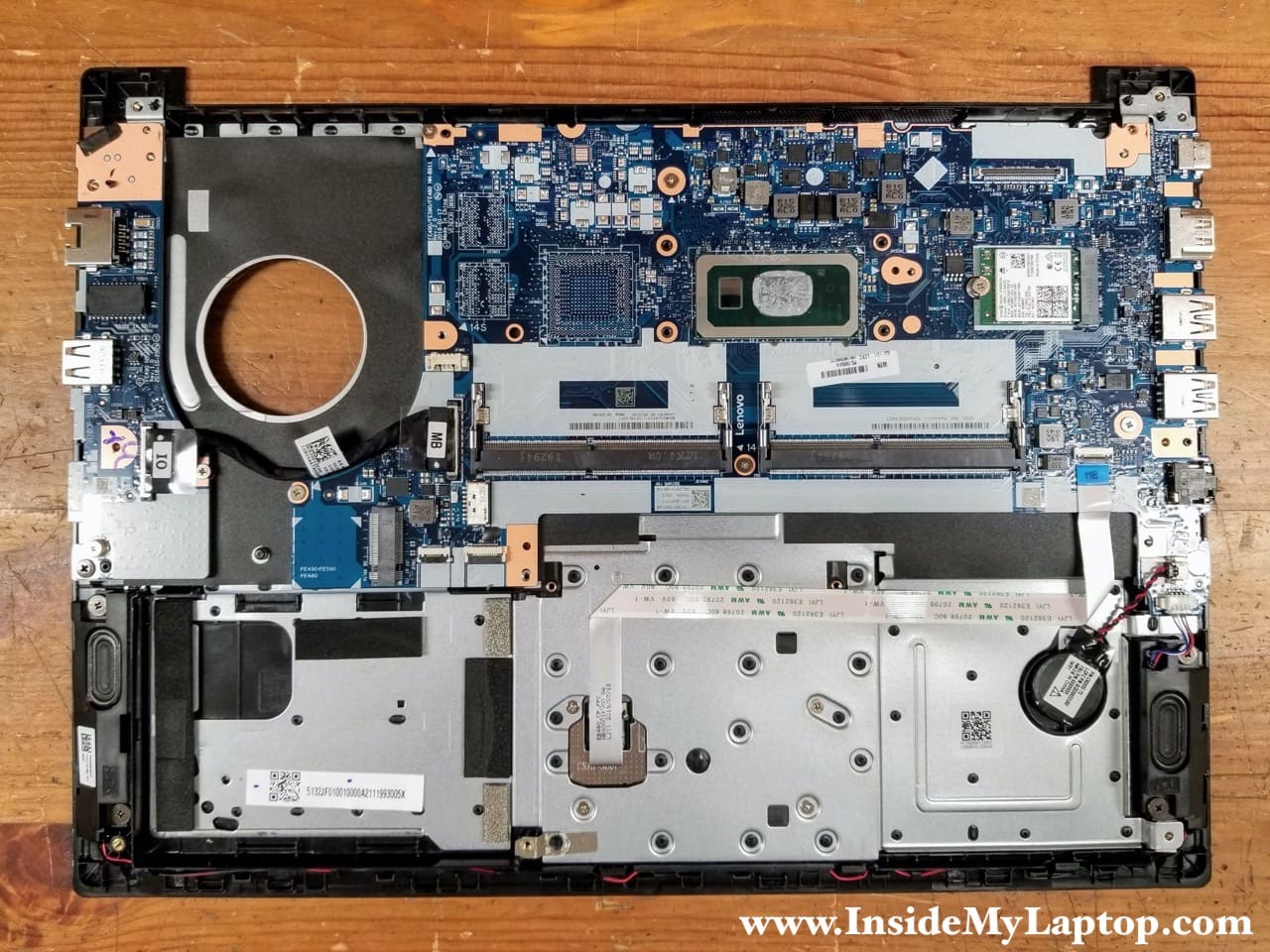
The display panel has been removed. I don’t have disassembly instructions at this time but you can find them in the service manual.

Here’s the top case with the display panel removed. The motherboard, I/O board and trackpad can be easily removed at this point.
Leo
Hi,
Thank you for the nice detailed post. Could you please tell me how to replace the touchpad? I could not see it in your photos. It’s not visible anywhere even after the battery is removed. Or can it be pried up from the top, like the keyboard?
IML Tech
When you remove the battery you’ll find four silver screws under the touchpad. I think you should be able to remove the touchpad after you remove those four screws.