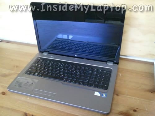
In the following guide I explain how to disassemble an HP G72.
This guid also works for Compaq Presario CQ72 models.
In this particular case I’m taking apart an HP G72-B57CL laptop.
I’ll go though the following major disassembly steps:
STEP 1-6: Removing the hard drive and optical drive. Accessing the CMOS battery, wireless card and memory modules.
STEP 7-15: Disconnecting and removing the keyboard.
STEP 16-20: Removing the top cover assembly.
STEP 21-26: Removing the motherboard.
STEP 27-30: Accessing the cooling fan and DC jack cable.
Before you start, make sure the computer is turned off. Also, I would recommend to keep track of all removed screws because they all have different length.
Draw a diagram with correct location of all removed screws. This will help tremendously during the reassembly process.
STEP 1.
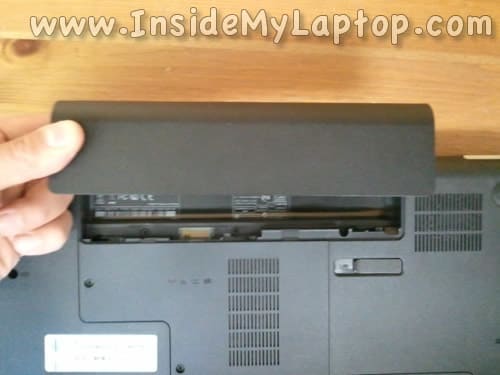
Unlock and remove the battery.
STEP 2.
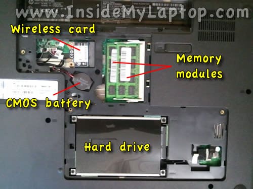
Remove four screws securing two service covers on the bottom.
Lift up and remove both covers.

Under these service covers you can access the following laptop components:
– Wireless card.
– Both memory modules.
– CMOS battery.
– Hard drive.
This laptop can handle 8GB (2x4GB) DDR3-12800 SODIMM memory modules.
STEP 3.
Remove four screws securing the hard drive assembly to the case.

STEP 4.
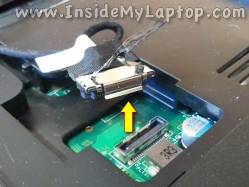
Disconnect the hard drive cable from the motherboard.
STEP 5.
Lift up and remove the hard drive assembly.
Upgrading this regular 2.5″ SATA hard drive to a 2.5″ SATA solid state drive will improve laptop performance significantly.

STEP 6.
Remove one screw securing the optical drive.
Pull the optical drive to the shown direction and remove it.
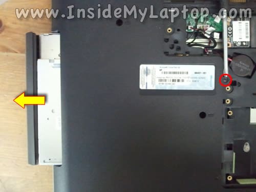
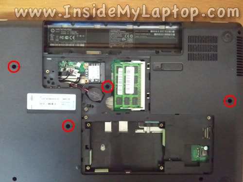
STEP 7.
Remove four screws securing the keyboard on the bottom.
STEP 8.
It was a little bit tricky to remove the keyboard from this HP G72 and here’s how I did it.
Insert a small screwdriver into the screw hole. I’m using a T6 torn for that.
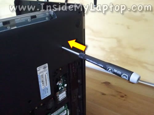
STEP 9.
When you push on the screwdriver you’ll one side of the keyboard will separate from the top cover.
Insert your fingers under the keyboard.
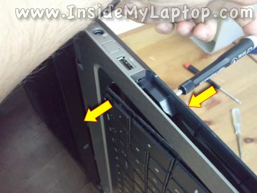
STEP 10.
Continue separating the keyboard from the top cover.
NOTE: in my case the keyboard was glued to the top cover with sticky tape. I had to wiggle the keyboard in order to unglue it from the top cover.

STEP 11.
Remove the keyboard and turn it upside down.
Be careful, the keyboard still connected to the motherboard.

STEP 12.
Before you pull the keyboard cable from the connector it’s necessary to unlock the connector.
In the following two steps I explain how to unlock the connector.

STEP 13.
Carefully lift up the left side of the cable retainer with your fingernail.
The retainer will open up at a 90 degree angle.
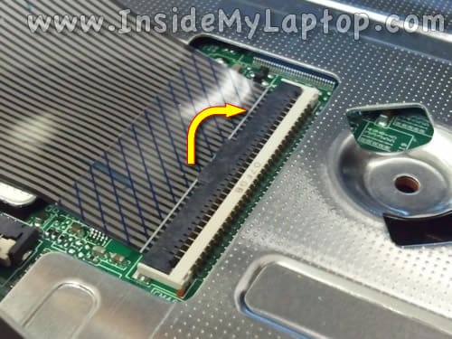
STEP 14.
On the following picture you can see the keyboard connector in the UNLOCKED position.
Now you can pull the cable from the connector.
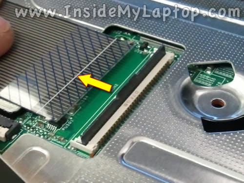
STEP 15.
Remove the keyboard.

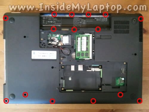
STEP 16.
Remove all screws from the bottom.
STEP 17.
Remove screws securing the top cover assembly.
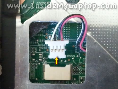
Disconnect the following cables:
1. Power button board cable.
2. Speaker cable.
3 and 4. Touchpad cables.
Unplug cables 1, 3 and 4 the same way you unplugged the keyboard cable in steps 13 and 14.
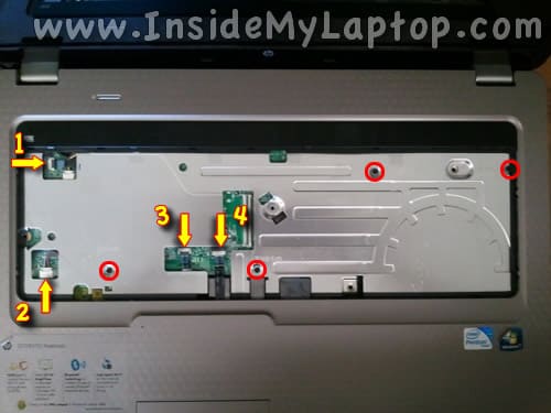
Here’s how to disconnect the speaker cable.
STEP 18.
Start separating the top cover assembly from the bottom cover using a piece of plastic. I’m using the guitar pick for that.

STEP 19.
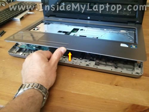
Continue removing the top cover assembly.
STEP 20.
Top cover assembly removed.
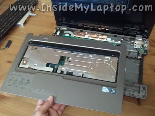
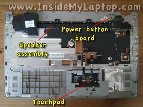
On the bottom side of the top cover assembly you can access the following components:
– Speaker assembly.
– Power button board.
– Touchpad.
Now we are going to disconnect and remove the motherboard.

STEP 21.
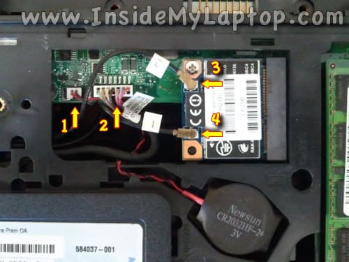
Disconnect the CMOS battery cable (1) and DC power jack cable (2) from the motherboard.
Disconnect wireless antenna cables 3 and 4 from the wireless card.
STEP 22.
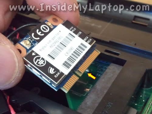
Remove one screw securing the wireless card and pull the card from the slot.
STEP 23.
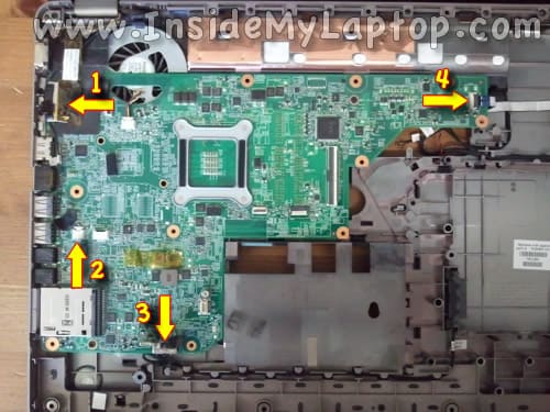
Disconnect the following cables from the motherboard:
1. Video cable.
2. Microphone cable.
3. Optical drive board cable.
4. USB board cable.
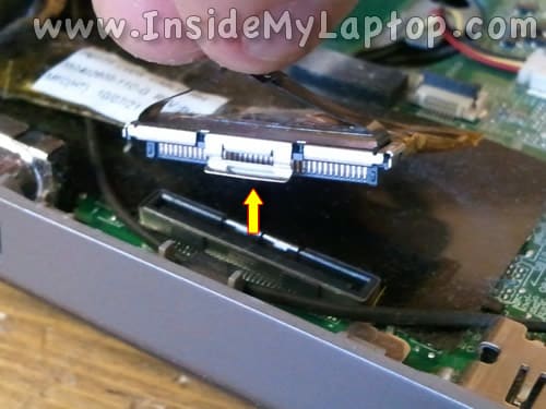
Here’s how to disconnect the video cable (1) and optical drive board cable (3).
STEP 24.
Remove three screws securing the motherboard.

STEP 25.
Start removing the motherboard from the right side.
Carefully lift up the right side of the motherboard and pull it from the bottom case.

STEP 26.
The motherboard removed.
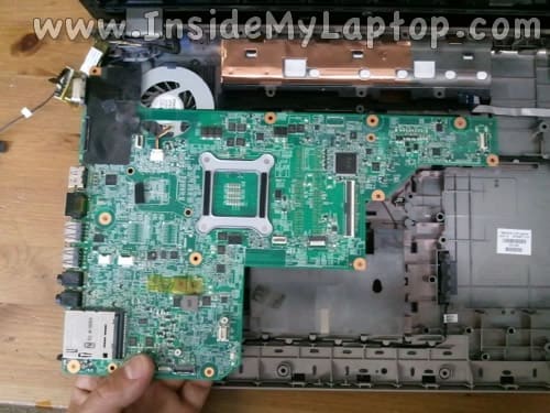
STEP 27.
Here’s the laptop base without the motherboard.
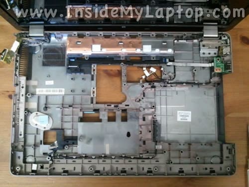
STEP 28.
If you are going to remove the cooling module assembly (cooling fan and heatsink) you’ll have to disconnect the fan cable which is shown on the picture below.
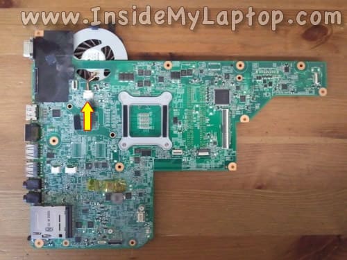
STEP 29.
You can access the cooling module assembly on the other side of the motherboard.
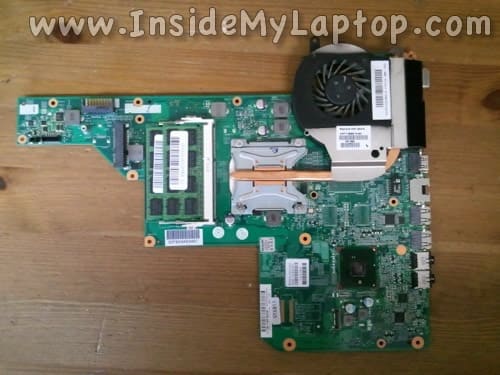
STEP 30.
The DC power jack located in the upper right corner of the laptop case.
The DC jack is attached to a cable.

Rick
We have a g72 259 WM laptop. local guy had for 5 weeks put new MB, power jack, power switch, nothing! I have no light at power plug nothing. Help!
Chiboy
Thanks for this steps.
My system is G72 but is a little bit different from yours, just a little.
It was overheating and i have bee trying to open it and clean the fan to see if that would help.
I’ve been used to assembling and disassemble desktop computers, but always scared of laptop unless if it’s just a ram or hard disk issue.
After following all the steps, i was able to disassemble my g72, and was really excited about it. After cleaning the fan, i put everything attached to the motherboard and found out it didn’t sit well. So i disconnected everything on the motherboard and found the cause near the vga plug and sited it well. But unfortunately, when i was trying to connect back a cable labeled “camera” I pushed it too much that it the connector came out of the motherboard and one of the four pins that it was attached to the motherboard with break. But i thought that since is just a camera cable i can do without the camera.
I carefully put everything else in place, after powering on the computer, nothing was showing on the screen, but it is a showing the light and power on sound with the fan working as well.
I disassembled back and check, the only thing that is not connected to the motherboard is the camera cable.
Do you think the problem is something else or can the camera cable stop the screen from showing when power on?
What do you think i should do?
The video cable is well connected.